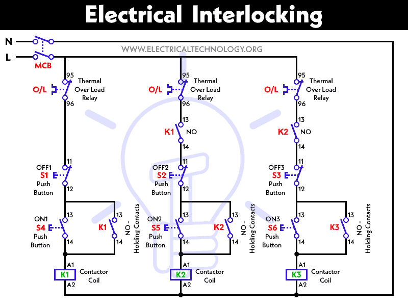
Tobi a homeowner from warri idaho. 3 phase dol starter control and power wiring diagram.

What Is Electrical Interlocking Power Amp Control Diagrams
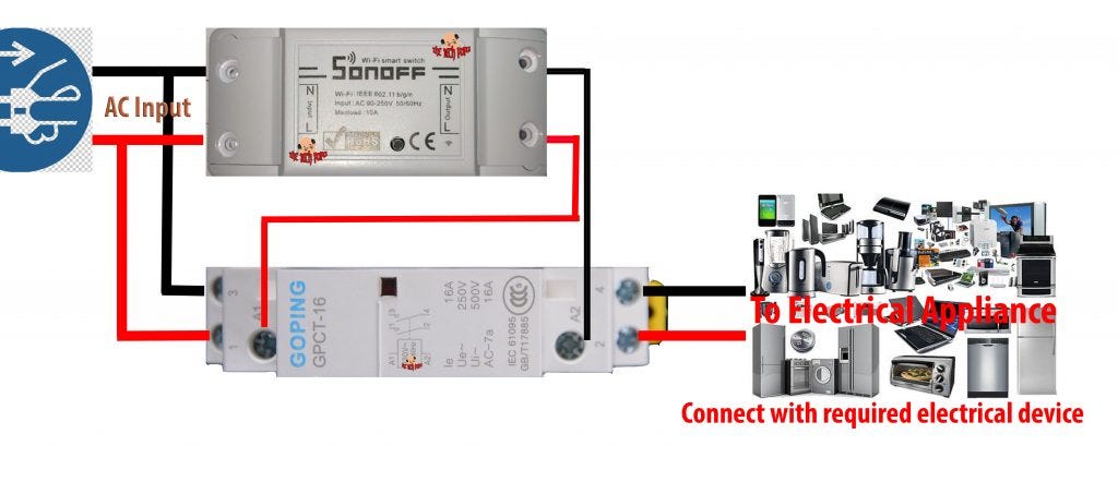
How to connect a contactor diagram. The most common for small direct on line starters dols is 415vac as this requires no neutral to be fed to the starter. A wiring diagram is a simplified standard pictorial depiction of an electric circuit. Attached is a pdf file with pictorial diagrams 1 of how you would connect the four most common variants of a dol starter. The contactor will have space for the red power wires coming in from the photocell circuit breaker and lights. This electrical question came from. Ryb electrical 88232 views.
Large electric motors can be protected from overcurrent damage through the use of. It shows the elements of the circuit as simplified forms and the power and also signal connections between the tools. The above diagram is a complete method of single phase motor wiring with circuit breaker and contactor. It reveals the elements of the circuit as streamlined forms and the power and also signal links between the gadgets. How contactors are wired to control single phase motors question. Match the input and output side of the wires if you are using fewer than the number of contactor terminals provided for the wiring you are connecting.
Water pump controller with float switch duration. A simple circuit diagram either of the two start buttons will close the contactor either of the stop buttons will open the contactor. A contactor is a large relay usually used to switch current to an electric motor or another high power load. How to connect a contactor. Collection of ac contactor wiring diagram. They show diagrams for 240 and 415 vac control.
Note that one one of the contactor acts as a switch for the start button. In the above one phase motor wiring i first connect a 2 pole circuit breaker and after that i connect the supply to motor starter and then i do cont actor coil wiring with normally close push button switch and normally open push button switch and in last i do connection between capacitor. A wiring diagram is a simplified traditional pictorial representation of an electrical circuit. Connect the power feed wires to the top side of the contactor to the terminals marked l. The black power wires will need to be tied together externally such as through a wire nut. See more about home wiring for idaho.
Collection of contactor wiring diagram ac unit. These too will be marked in the same numerical order as in step 4 above l1 l2 and l3. The lights connect to the output ports on the contactor. How do i connect a single phase contactor to power an electric motor.


