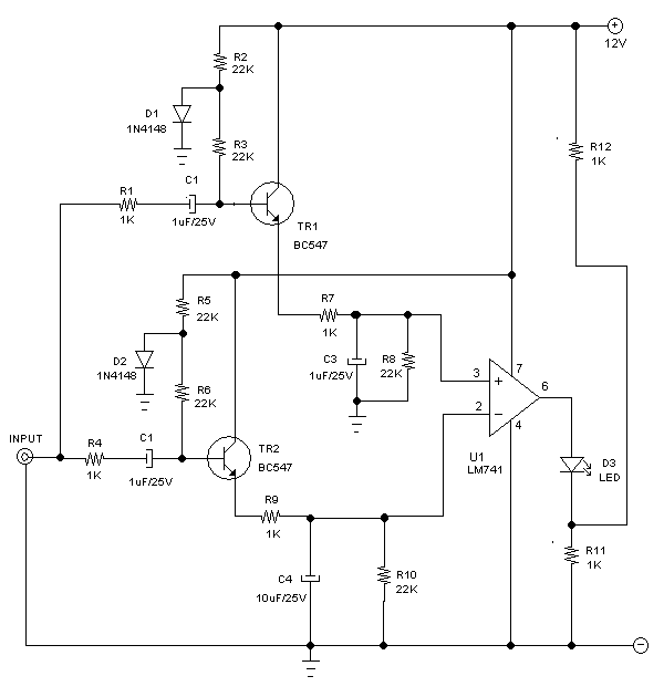
See more ideas about circuit diagram circuit electronics circuit. The lm1830 fluid level detector circuit is a device intended to signal the presence or absence of aqueous solutions featuring low external parts count wide supply operating range internally regulated supply and ac or dc output.

Fluid Level Control Schematic Diagrams
Level control circuit diagram. This page provides a reference design for an arduino based circuit showing the simplest device embodiment including pressure sensing. This circuit uses two level switches to maintain the level within a given range. Automatic water level controller circuit leaf switches s1 and s2 used in tape recorders are fixed at the top of the sensor units such that when the floats are lifted the attached 5mm dia. Approx aluminium rods push the moving contacts p1 and p2 of leaf switches s1 and s2 from normally closed nc position to normally open no position. Joydeep kumar chakraborty. The arduino mega is connected to a prototype circuit board that interfaces with the screen buttons and potentiometers.
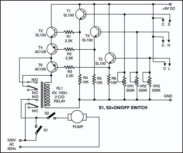
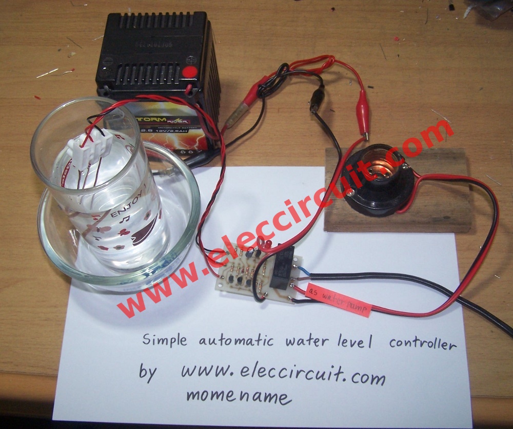
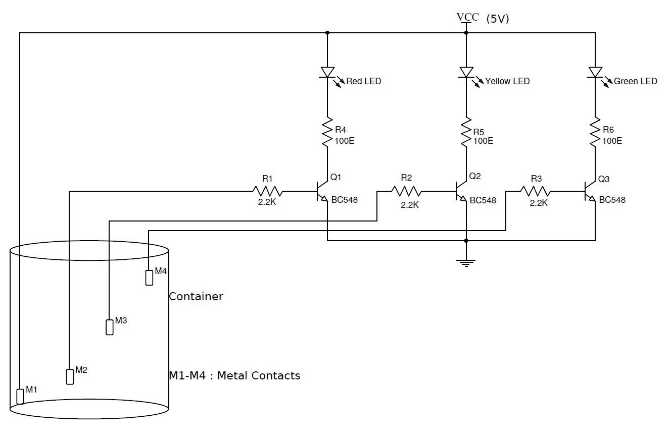
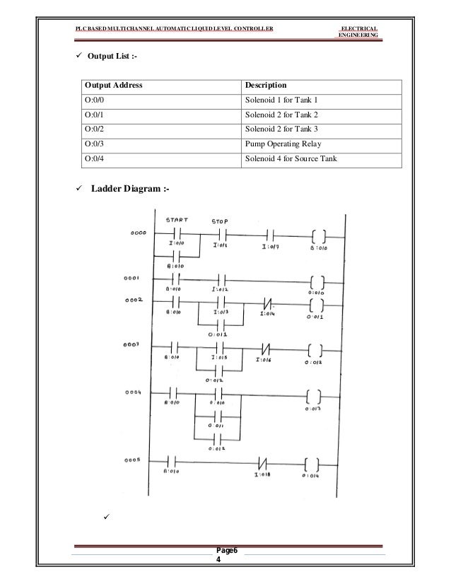
This is a typical relay based control system that is used to control liquid level in the tank. The circuit automatically switches on the pump when water is low in the tank and switches the pump off when water reaches a predetermined mark. Here is a simple level switch circuit that switches on one relay and switches off another relay when the fluid level exceeds the set limitthis circuit is a modification of the simple water level indicator previously postedwhen the water level touches the probes positive supply is connected to the base of q1 through fluidthis makes transistor. Electromechanical relay control systems were one of the first types of control systems used in the process control industry to perform onoff control. In a typical application where the device is employed for sensing low water levels in a tank a simple steel. This is a circuit for water level controller is based on transistors and relays.
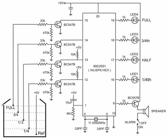
Jun 30 2020 explore juni joness board circuit diagram on pinterest. The new circuit diagram for the logic side of the circuit is as follows. Fluid level control schematic diagrams with lm1830.
