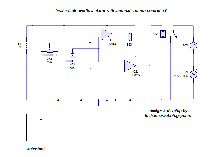
The water level is sensed by two floats to operate the switches for controlling the pump motor. It does not require all time electricity and also high water pressure.

Water Level Control Circuit Figure 3 Flowchart Water Level
Water level control circuit diagram. Some homes have a large water tank on high then pumping up the put on hold. As a result transistor t1 gets forward biased and starts conducting. Water level indicator circuit using uln2003 ic. Also read the interesting concept about how water level alarm circuit works using 555 timer. The circuit uses 6 transistors 1 ne555 timer ic a relay and few passive components. Such sensors are more reliable than.
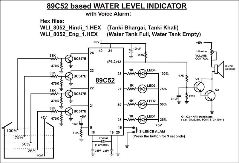
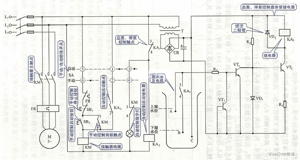
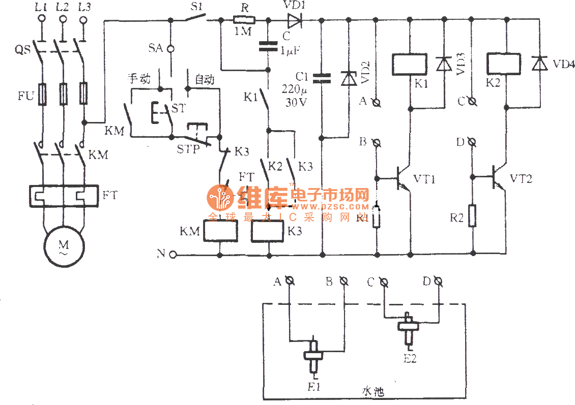
When you want to use just to turn on the tap at the bottom. Water tank overflow is a common problem which leads to the wastage of water. The water level controller circuit is a simple mechanism to detect and control the level of water in the overhead tank and also in the other containers. The circuit is completely automatic which starts the pump motor when the water level in the over head tank goes below a preset level and switches off the pump when. Water level controller circuit water level controller circuit. We can design the water level indicator circuit using uln2003 ic as the main component.
Algorithm for water level controller circuit first configure the controller pins p00 p01 and p02 as inputs and p07 as output. Continuously check the water level input pins p00 p01 and p02. Automatic water pump controller circuit diagram. A simple but very reliable and effective water level controller circuit diagram is shown here. Automatic water level controller circuit. Now initialize the lcd.
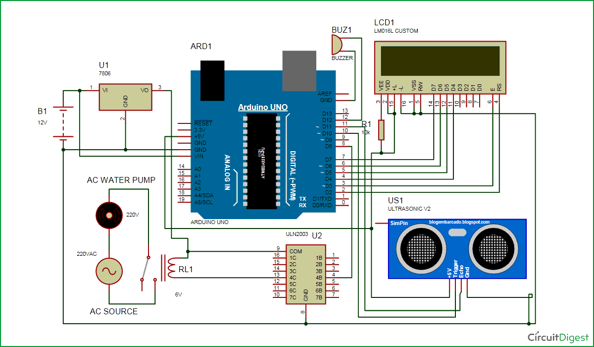
When there is enough water in the underground tank probes c and s are connected through water. The low level and high level probes in the overhead tank are marked l and h respectively. This arrangement is encased in a pvc pipe and fixed vertically on the inside wall of the water tank. Though there are many solutions to it like ball valves which automatically stop the water flow once the tank gets full. Before starting the design process of this circuit lets give you a brief explanation of the uln 2003 ic. Here is a simple level switch circuit that switches on one relay and switches off another relay when the fluid level exceeds the set limitthis circuit is a modification of the simple water level indicator previously postedwhen the water level touches the probes positive supply is connected to the base of q1 through fluidthis makes transistor.
Convenient and savings but. Each sensors float is suspended from above using an aluminium rod.

