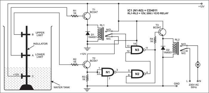
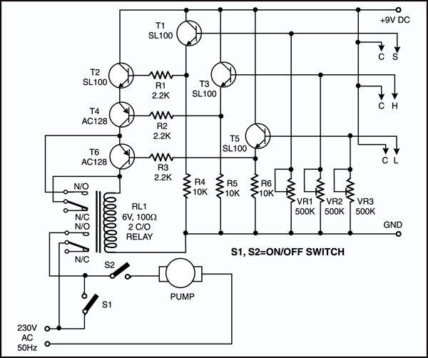
The a to e wire ends of the circuit are placed in the shown order inside the overhead tank. It has pump running low level high level signals.
Versatile Water Level Controller Full Circuit Diagram With
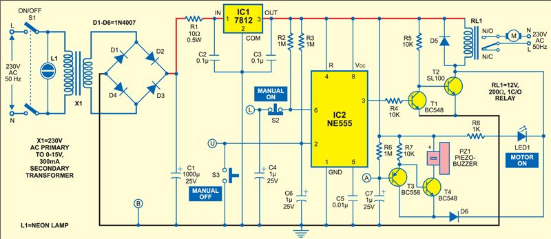
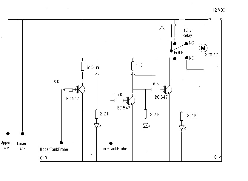
Water tank level control circuit diagram. Throughout the above article we have discussed the two methods to design this low cost water level indicator circuit. If the circuit is constructed as shown above if initially the water in the tank is below minimum threshold and the system is turned on the pump will start pumping water into the tank and no led will come on but immediately water reaches the minimum threshold the red led will come on indicating that the tank is one third full. This project also work for save water and save electricity. How the operation of relay based onoff control system is. This circuit controls the pump stopped working. This arrangement is encased in a pvc pipe and fixed vertically on the inside wall of the water tank.
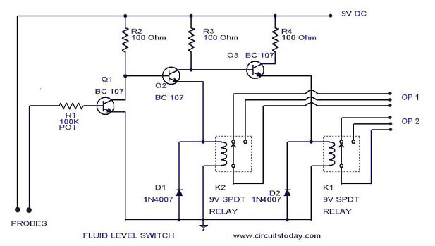
If the level of the water reaches high point the pump will started so that the water can be drained and thus lowering the level. When the water a full tank. This water level indicator circuit can also be used for a liquid level indicator in huge containers. Automatic water pump control circuit help to control water tank overflow. Here is a simple level switch circuit that switches on one relay and switches off another relay when the fluid level exceeds the set limitthis circuit is a modification of the simple water level indicator previously postedwhen the water level touches the probes positive supply is connected to the base of q1 through fluidthis makes transistor. Then we use the water out.
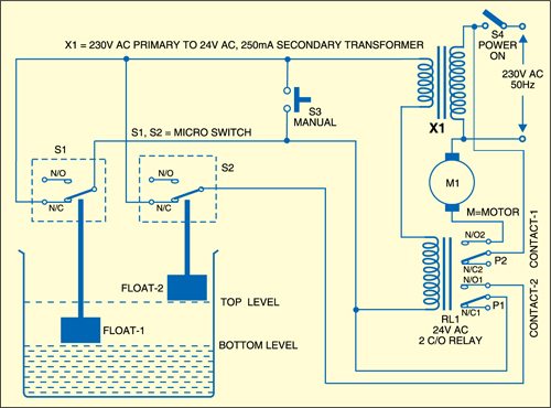
But i have to control the water level in the tank is fixed is water must not out or overflow which is a waste of time look at the pump. This panel contains leds to show the status of the water level control. This project is environmental related project. You can use up. Each sensors float is suspended from above using an aluminium rod. To explain how it operates the images below will show a ladder diagram left side figure and a pictorial diagram right side figure for a visual concept of what happens with.
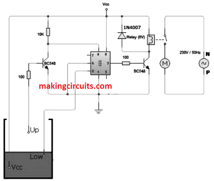
This is the circuit to determine the level of water in the process tank using relay based onoff control. It can also be used in fuel level indicator in motor vehicles. Such sensors are more reliable than. The water level is sensed by two floats to operate the switches for controlling the pump motor. Automatic water level controller circuit. As a result transistor t1 gets forward biased and starts conducting.
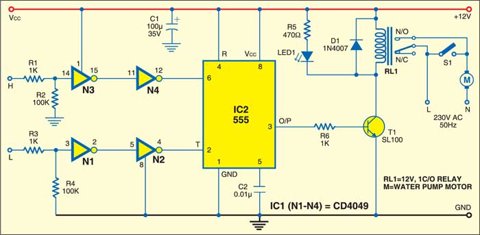
I have the ideal to create this automatic water pump controller project. The low level and high level probes in the overhead tank are marked l and h respectively. The level of the water is indicated by the leds which light up as the water climbs inside the overhead tank. Water level controller circuit water level controller circuit. When the water level reaches low level then pump will be stopped. Over head tank water level indicator and motor protector.
The above circuit has been presented on request from one of my followers prateek. When there is enough water in the underground tank probes c and s are connected through water.
Gallery of Water Tank Level Control Circuit Diagram


.bmp)