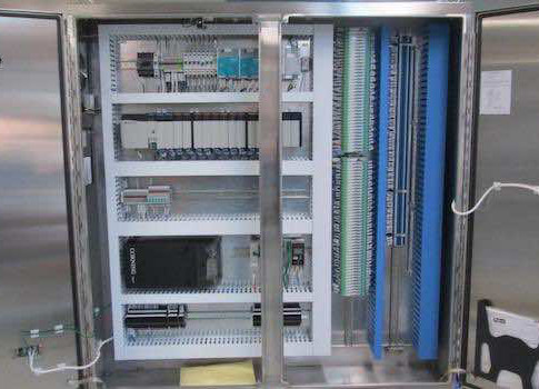
Control panel design for industrial equipment and machinery is an important undertaking resulting in an interface designed to control a machine or process. Each page of the wiring diagram shows the exact wiring for different sections of the control panel.

Industrial Control Panels Faqs Below Is A List Of Industries
Industrial electrical panel wiring diagram. How to wire an electrical panel square d duration. Three phase electrical wiring installation in home iec nec. Electrical panel emt run armoured cable run bx 4x4 junction box 10 12 21 mm 21 mm figure 2circuit drawing line diagram. How to connect a portable generator to home supply system three methods a simple circuit diagram of contactor with three phase motor. Its not a simple matter of selecting an appropriate enclosure and a back panel that houses the electrical hardware. Wiring diagrams help technicians to see how the controls are wired to the system.
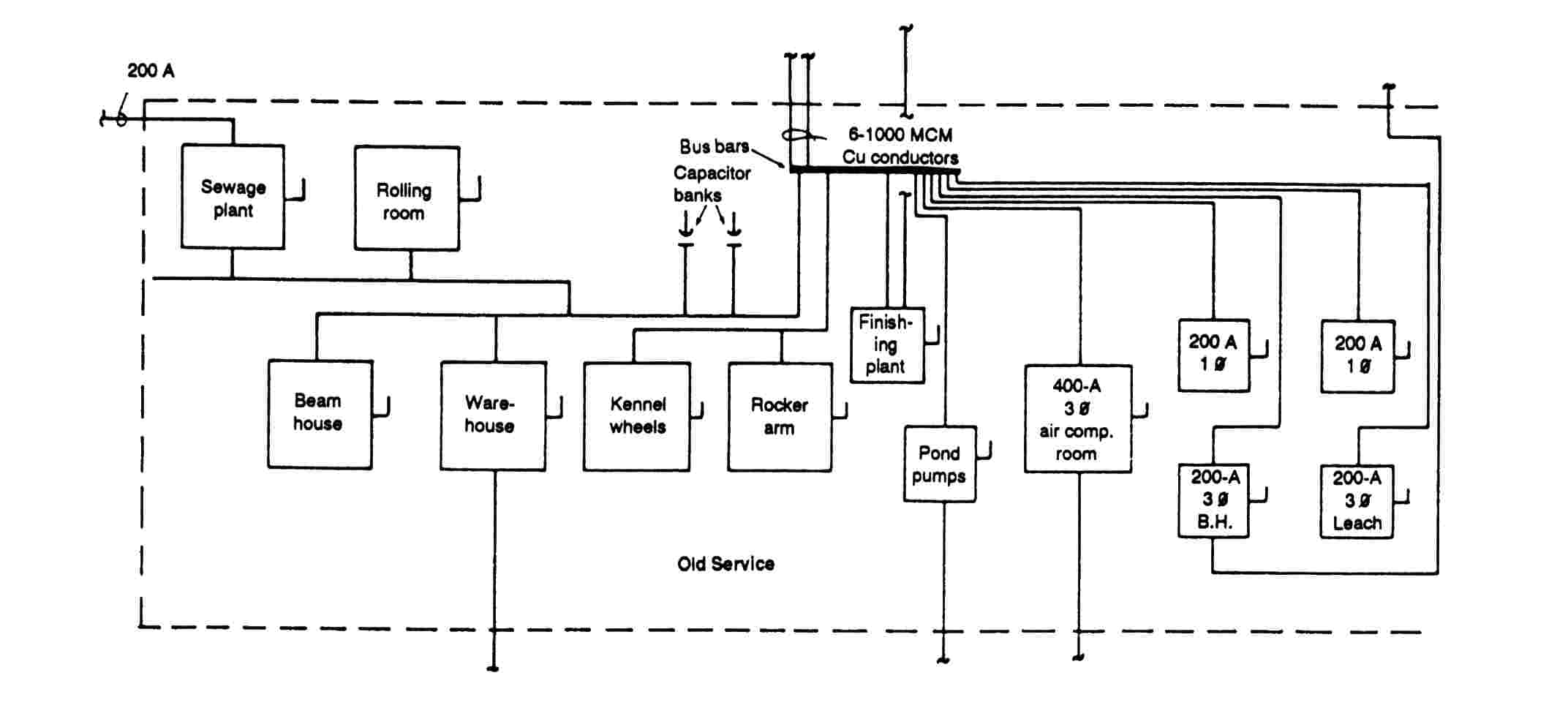
The one line diagram is similar to a block diagram except that electrical. The electrical design for each machine must include at least the following components. It is a 480 volt delta three phase system. You may also read. Three phase dol starter control overload indicator power wiring diagram duration. Electrical wiring diagrams of a plc panel.
Figure 7 shows the system used for large industrial plants where most of the load consists of motors. Drilling holes in an ul 508a industrial electrical control panel. All the wiring that you see in the panel is done based on the wiring diagram. These tags can be found in the panel as well. Figure 6 is a diagram for a 480276 volt three phase four wire system. Each page of the wiring diagram shows the exact wiring for.
Transformers are used to get 120 volt single phase circuits. This is what we draw using autocad electrical. This type of diagram is like taking a photograph of the parts and wires all connected up. Din rail cutter a big time saver when building industrial electrical control panels. Industrial control panel design schematics. This system serves hotels shopping centers etc.
One line diagram of simple contactor circuit. An important part of a professional industrial control panel. Each of the wires in the wiring diagram has a tag number. A one line diagram or single line diagram is a simplified notation for representing an electrical system. Industrial control panels in depth look part. Many people can read and understand schematics known as label or line diagrams.
This is what we draw using autocad electrical. Transformers to step down ac supply voltages to lower levels. In an industrial setting a plc is not simply plugged into a wall socket. All the wiring that you see in the panel is done based on the wiring diagram. Wire ferrules when to use how to crimp insulated vs non insulated and ul 508a guidelines.


