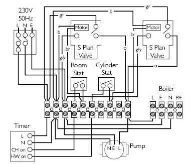
Y plan system schematic. A wiring diagram is a simplified traditional pictorial representation of an electric circuit.

Wiring Diagram Boiler Electrical Wires Amp Cable Schematic
Boiler electrical diagram. Showing flow from boiler to y plan or mid position diverter valve and then onto heating or hot water circuit. Most of the wiring diagrams are for natural gas powered steam boilers. A wiring diagram is a simplified conventional photographic depiction of an electrical circuit. This is a diagram that illustrates the way a boiler works. Not a bad link though. August 17 2018 by larry a.
It shows the elements of the circuit as streamlined shapes as well as the power as well as signal connections in between the gadgets. This is fine if the boiler is 120 v. Lets first see some basic information about boilers. Steam boiler or simply a boiler is basically a closed vessel into which water is heated until the water is converted into steam at required pressure. Ct 6 10 15 and 25 boiler wiring diagram. It is part of the instruction that should always be provided by the manufacturer of the appliance you are about to buy.
Ct 35 and 50 boiler wiring diagram. Collection of boiler wiring diagram for thermostat. This is most basic definition of boiler. Working principle of boiler. Central heating boiler electrical wiring connection diagrams for electricians electricians blog. Jan 19 2012 16 it rises from the past.
Lets view the scheme and find out more about how condensing and non condensing units operate. The diagram above is showing the boiler parts which are mandatory for the design and operation of steam boiler. Jan 19 2012 15 blimey i hope hes not still trying to wire this boiler upcensored. Hrt 20 and 30 boiler wiring diagram. Boiler or more specifically steam boiler is an essential part of thermal power plant. Ct 6 and 25 boiler wiring diagram.
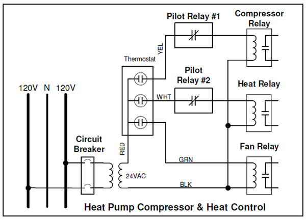
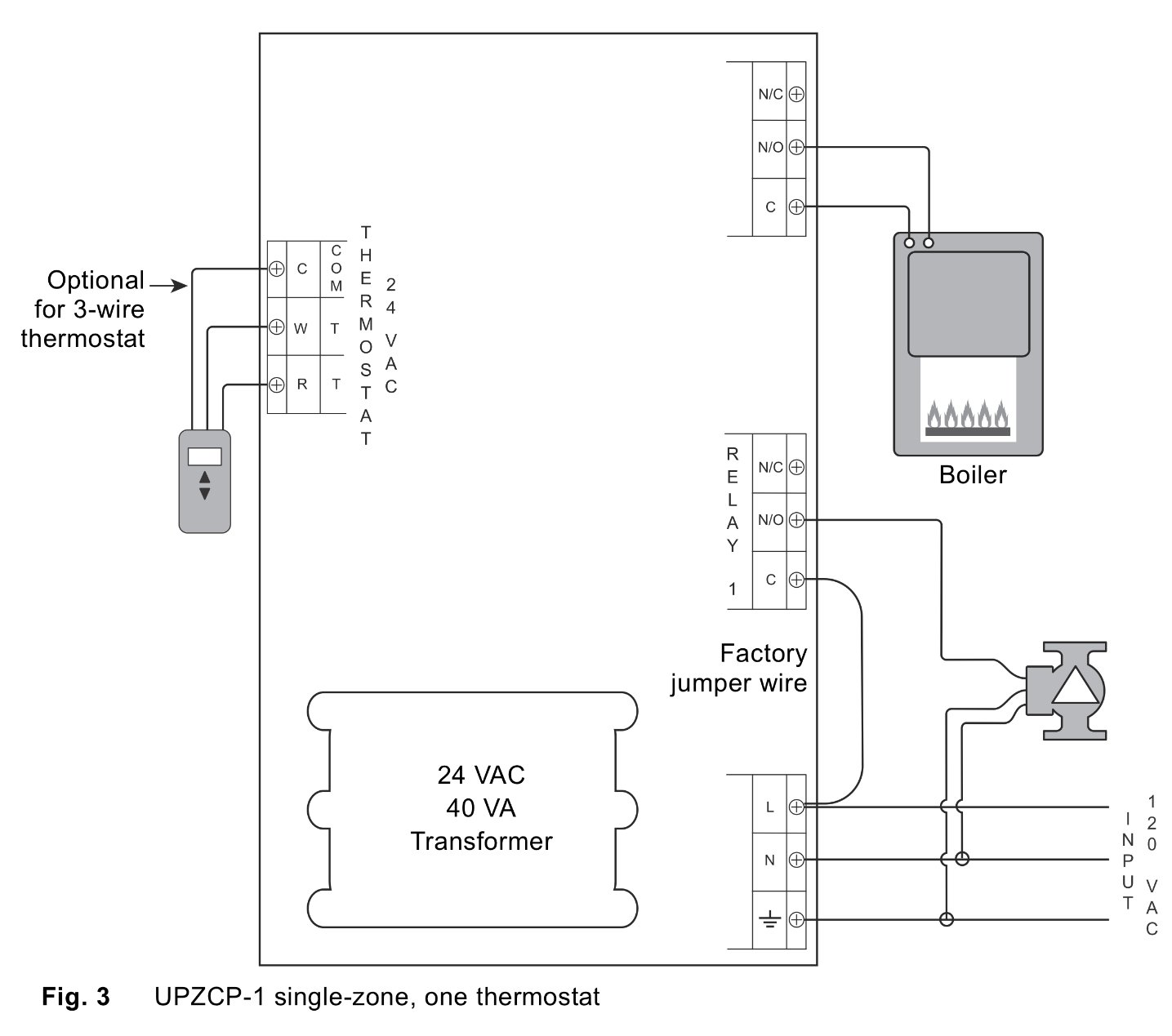
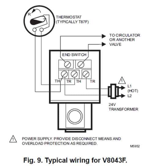
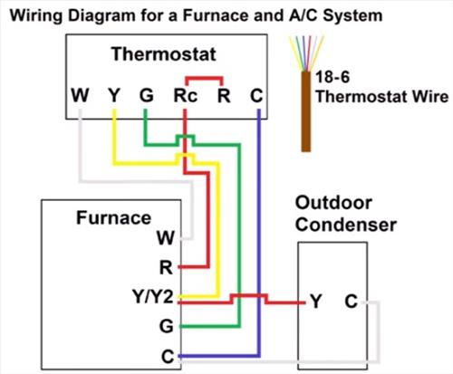
Wellborn assortment of steam boiler wiring diagram. To get from 120 v to 24 v we use a transformer. Wiring diagrams for oil burning and water boilers are noted. It reveals the parts of the circuit as simplified shapes and also the power and also signal connections between the gadgets. This wiring diagram shows 120 v coming from l1 of a circuit breaker through a switch powering a boiler control and returning through l2 back to the neutral bar of the circuit breaker box. System wiring diagrams.
However most gas boilers you will be working on have 24 v controls. Hence each boiler part plays important role and everyone interested to know more about boilers can learn from this page in the last section.
