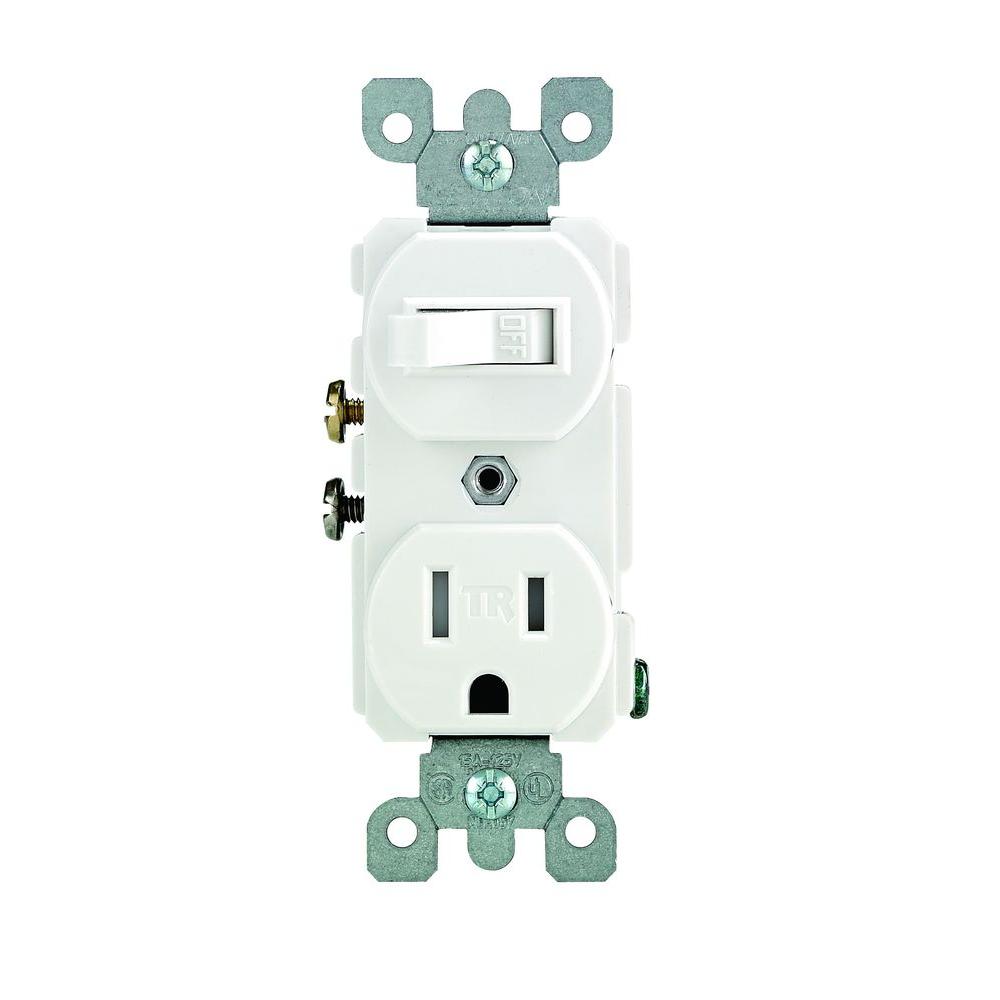
In the first case the switch controls the outlet and nothing else. You can wire a switchoutlet combo in one of three ways.
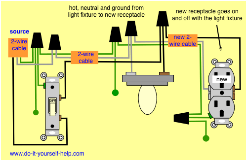
Light Switch Receptacle Wiring Diagram Fiat 7 Mareikekirsch De
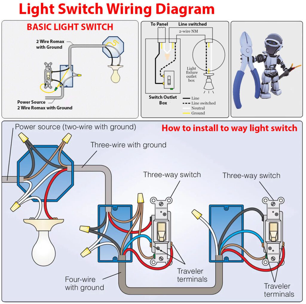
How to connect a light switch to an outlet diagram. Wiring an outlet and a light switch mid circuit. Twist the white wires together and cap them and connect the ground wires to the ground terminal. Wiring a light switch diagram 1. Connect the black wire to one of the switch terminals and the black wire going to the light fixture to the other switch terminal. 3 way switch diagram. In this special case wiring diagram both light and ordinary outlet is connected to the load terminals of gfci.
Fully explained light switch wiring diagrams. This electrical wiring question came from. Is it possible to wire a switch for a light and at the same time connect an outlet to the switch that will not power off and on with the switch. Wiring a gfci combo switchoutlet with protected light outlet receptacle. How to wire a switch. Electrical outlet with light fixture wiring diagram.
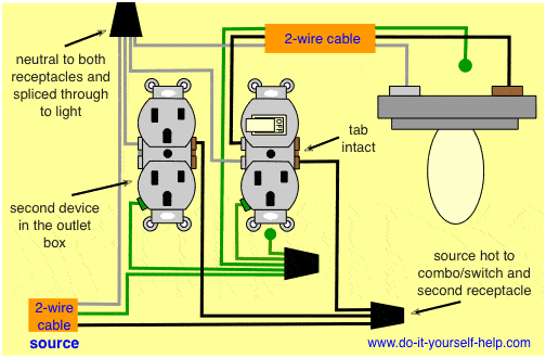
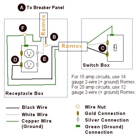
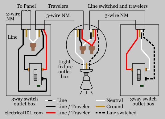
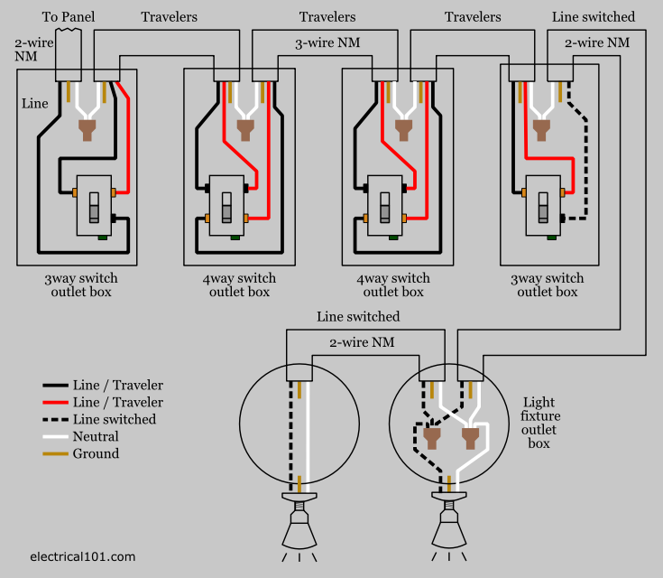
3 way switch diagram. This wiring allows the electricity to continue from the receptacle on to any other outlets in the circuit and it provides a switch for controlling a light fixture or other load such as. The light onoff operation can be controlled through the gfci switch while the ordinary outlet is directly connected to the gfci load terminals. In response to the requests for this information i have developed a comprehensivestep by step guide designed to walk you through the identification and wiring of your 3 way switches. This diagram illustrates a switch and receptacle in the same outlet box located in the middle of the circuit. When thats done you can treat the cable coming from the outlet into the switch box as a regular line cable.
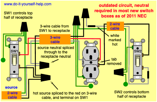
The source is at the outlet and a switch loop is added to a new switch. This topic explains 2 way light switch wiring diagram and how to wire 2 way electrical circuit with multiple light and outlet. The hot source wire is removed from the receptacle and spliced to the red wire running to the switch. To make this happen connect the black circuit wire to the brass screw on the device the white wire to the chrome screw and the ground wire to the green ground screw. The neutral earth and live wire should be connected to the box. Mike a handyman from fort dodge iowa.
Connect the wires to the receptacles. Wiring an outlet to a switch loop. Wiring a switch with an outlet. This wiring diagram illustrates adding wiring for a light switch to control an existing wall outlet. Rj45 wiring diagram ethernet cable.
