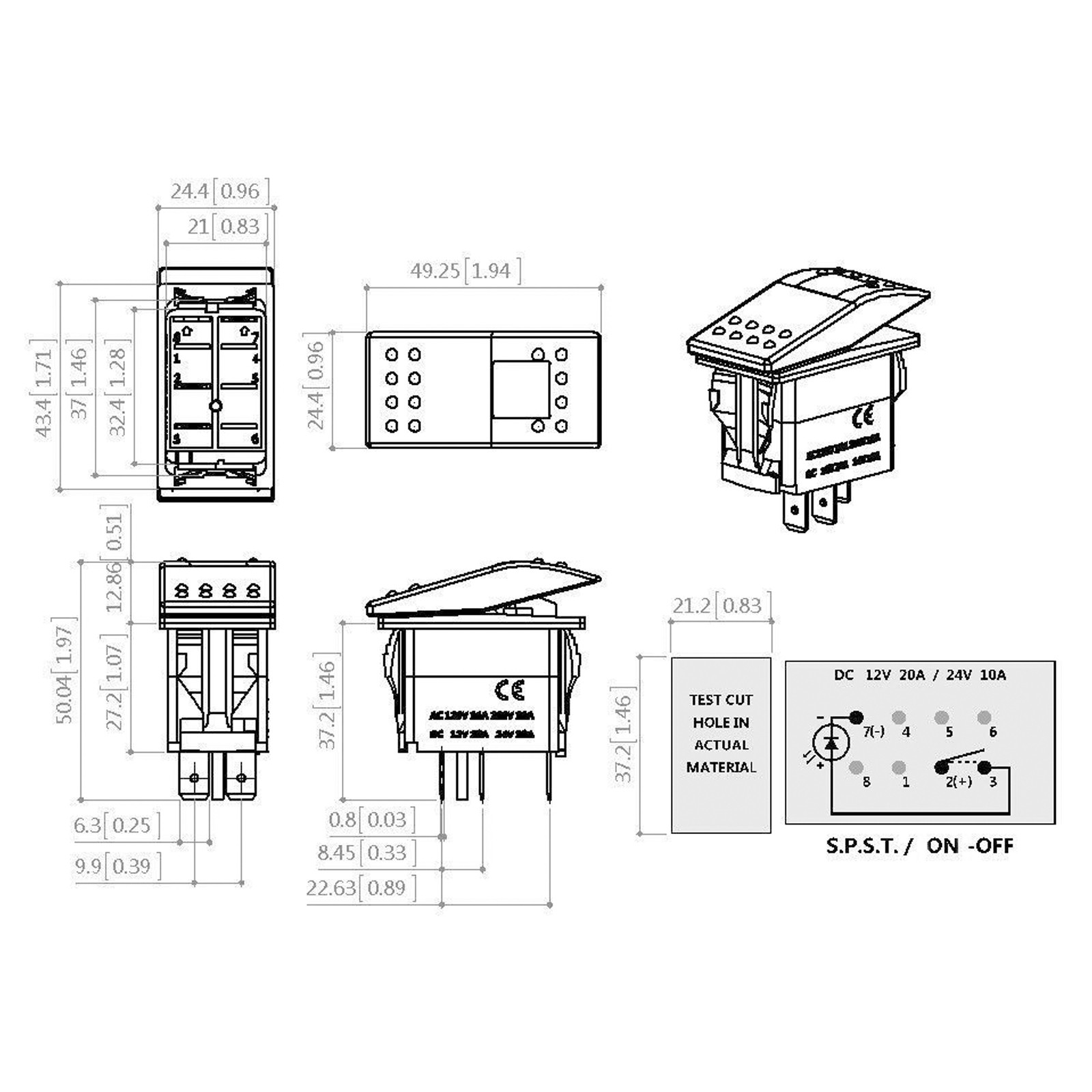
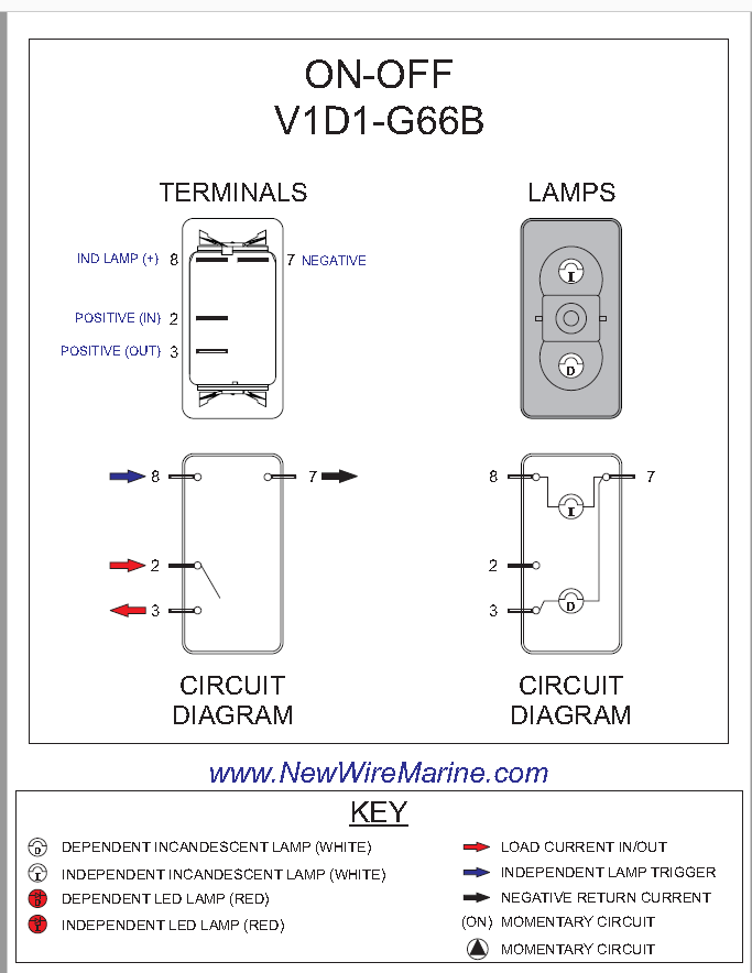
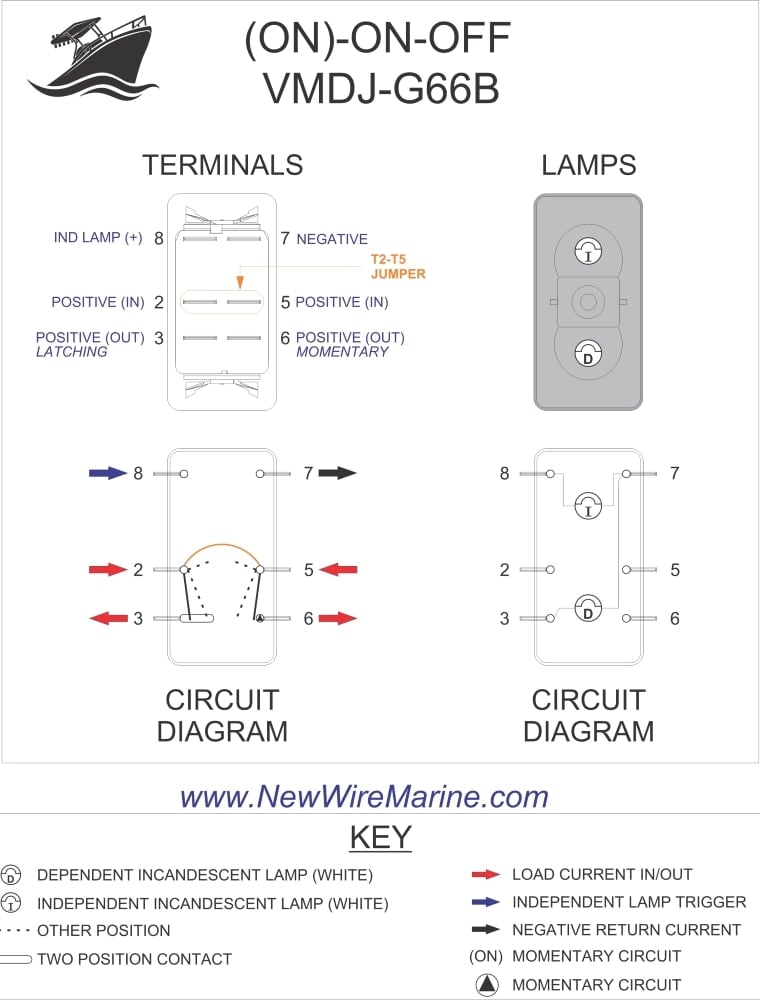
How to wire a dual led rocker switch 5 pin duration. The wiring diagram below will demonstrate how to to wire and power this 12v 20amp on on off 3 way carling contura rocker switch.

Details About 16mm Round On Off Circle Rocker Switch 3 Way 3 Pin 3a Diy Electrical Project
How to wire a 3 pin rocker switch. An illuminated rocker switch is like a spst toggle switch with an extra terminal which allows the light to work. It is off at the bottom on in the center and momentary on at the top. Rocky x tv 227699 views. Pin 3 is where the switch is either connected to ground or left open. We will now go over the wiring diagram of a dpdt toggle switch. If not the arrangement wont function as it should be.
Pin 3 6 to devices powered when rocker is in position 3. Aurora wiring harnesses are set up as black groundnegative red positive blue power to lighting product. How to wire 3 prong rocker led switch duration. Pin 1 4 to devices powered when rocker is in position 1. A dpdt toggle switch has 6 terminals. If you are trying to convert a 3 pin light bar switch to a 5 pin rocker switch then please read below.
Pin 1 is where the rocker switch receives the input power. Each part should be placed and connected with different parts in particular manner. Attach the blue jumper connector to the opposite corner and the brown jumper to the other corner to form an x across the switch. Pin 2 is where the accessory that the switch is going to turn on is connected. The vmdj is a unique dpdt momentary rocker switch. Below is the schematic diagram of the wiring for connecting a dpdt toggle switch.
Dpdt toggle switch wiring. To wire a 3 pin switch to a 5 pin rocker switch you need to find out what your 3 wires do. This rocker is perfect for an engine offrunstart switch. Below is a pictorial representation of the schematic diagram. Device 1 2 are lights on the front end device 3 4 are lights on the rear end. You might want to review the article on toggle switch wiring before proceeding.
Terminals 3 and 4 represent the toggle switch. These terminals receive the power necessary to drive the loads on. Attach the main blue terminal to one of the poles on the side attach the main brown termainl to the pole right next to it. 3 pin rocker switch wiring diagram 3 pin rocker switch wiring diagram every electric structure is made up of various distinct pieces. Battery power controlled by key switch. Also relays can be used to switch higher draw accessories to reduce switch load and voltage drop.
This translates into the following model in a real life rocker switch. Second devices on pin 2 5 should be from keyed power under radiator.


