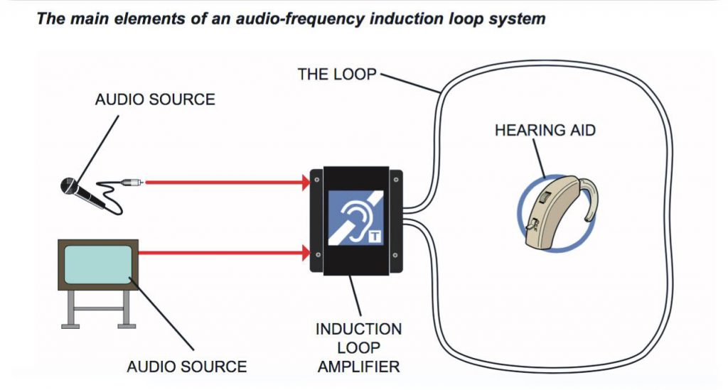
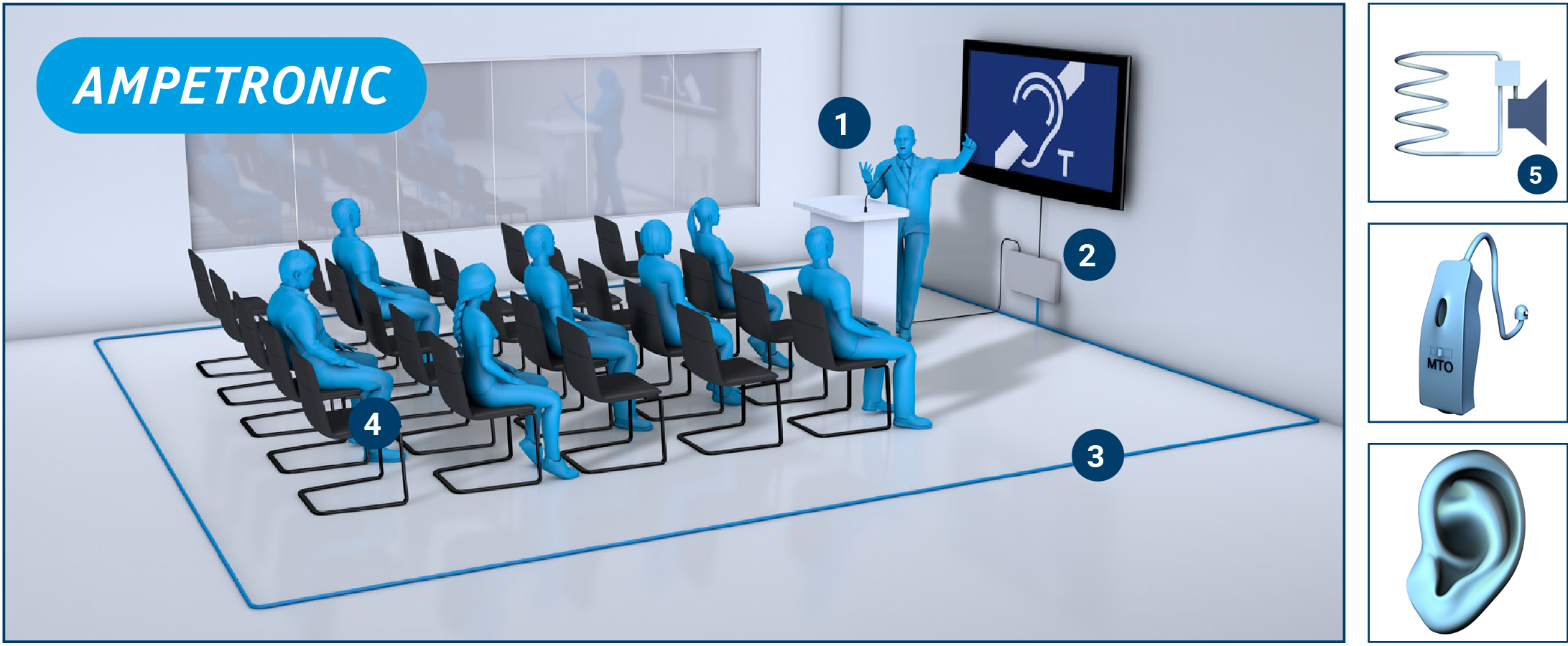
T loop systems also called induction loop amplification systems work by the process of induction explained below. When audio is input into the amplifier this magnetic field fluctuates.
Inductive Loop Vehicle Detector V2 1 Elektronika Ba
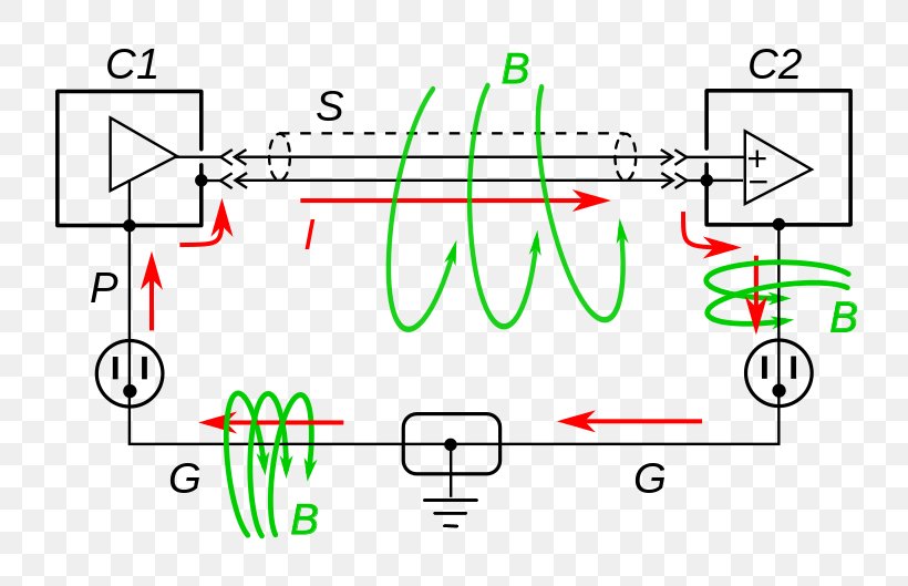
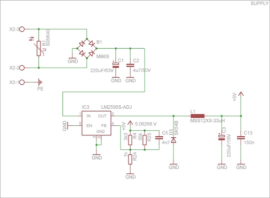
Induction loop wiring diagram. These fluctuations or magnetic waves are picked up by t coil equipped devices such as a. Single phase motors are inherently noisier and less smooth running than polyphase motors. It is preferable that the combination of the loop and lead in inductance values has a minimum of approximately 50 microhenries for stability. Pda induction loop amplifiers are designed to drive into loops with dc. What is the minimum acceptable loop inductance. Loop wiring diagram type r1 and r1w loop wiring diagram type r2 and r1wa offset crimps splice typ typ 2csh cable junction box typ marking sleeve loop number type r2 layout shown speed loop wiring diagram type r1s s sb fb sa fa junction box f b offset crimps splice typ a typ marking sleeve typ 2csh cable loop number notes 1.
When an electrical current is amplified and passed through a loop of wire a magnetic field is generated around the wire that varies in direct. Induction loop systems aims to provide straightforward explanations of the technology involved together with hints tips and advice on best practice installation. Because there is a backward rotating component of flux there are pulsating torques so the torque speed curve is really just a representation of the average. An induction loop system consists of one or more loops of wire driven by an amplifier to produce a magnetic field. Capacitor start induction motor csim circuit wiring diagram and torque speed curve. An inductive loop detector will tune to inductance values ranging from 20 to 1000 microhenries.
In the uk the installation of induction loop systems is governed by bs7594 the code of practice for audio frequency induction loop systems and en60118 4 magnetic field. Audio induction systems operate on the electronics principle of electro magnetics. Voltage mode amplifiers are unlikely to be able to operate safely into less than 20 ohms. Resistance in the range 02 to 20 ohms ideally 10 ohm and to not distort or overheat.
Gallery of Induction Loop Wiring Diagram