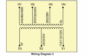
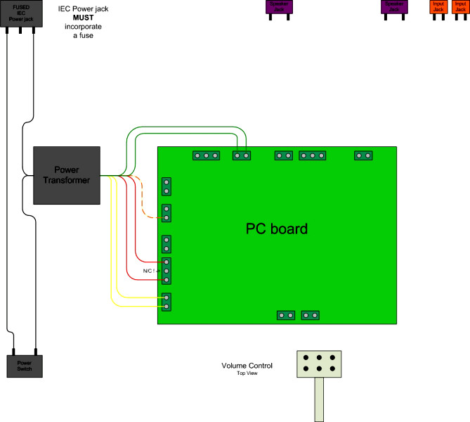
It shows the components of the circuit as streamlined forms and the power and signal connections in between the devices. It combines multiple primary voltages with one or more secondary voltages all in a single transfomer.

Pin Auf Schema Cablage
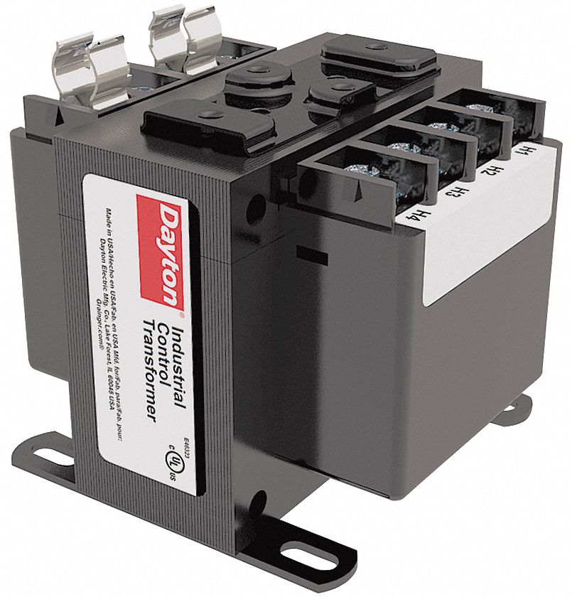
Industrial control transformer wiring diagram. The multitap control transformer was designed to respond to the increased need for voltage and stock flexibility. Control transformers are also known as machine tool transformers industrial control transformers. The components of the diagram will include a transformer low voltage source thermostat switch humidistat switch low voltage damper actuator load low voltage light load and a contactor with a low voltage coil load. Industrial control transformers icts entering the european union eu after. Figure 4 control power transformer wiring diagram. With a 50 60 hz operation standard transformers are designed for loads requiring.
The leads from the primary of the transformer are connected to l1 and l2 on the starter. Sp1500acp hammond control transformer open core 15 kva 1 phase 480600 vac primary 120240 vac secondary 60 hz panel mount. Performance meets or exceeds ansinema st 1 requirements. Tutorial for installing the proper included va rated jumpers on square d 9070 series industrial control transformers machine tool. A wiring diagram is a streamlined traditional photographic depiction of an electric circuit. Variety of control transformer wiring diagram.
A wiring diagram is a simplified traditional photographic depiction of an electrical circuit. To learn more please visit the schneider electric faq. A control transformer is an isolation transformer designed to provide a high degree of secondary voltage stability regulation during a brief period of overload condition also referred to as inrush current. Variety of industrial control transformer wiring diagram. Eaton offers a complete line of type ap mte and mtk industrial control transformers which provide stepped down voltages to machine tool control devices. Each unit must pass rigid tests for turns ratio insulation continuity and over potential.
What is a control transformer. It reveals the components of the circuit as simplified forms and also the power and signal links in between the gadgets. Industrial control transformer wiring diagram building wiring layouts reveal the approximate areas and affiliations of receptacles illumination as well as irreversible electrical solutions in a building. Interconnecting cable routes could be revealed around where specific receptacles or components need to be on a typical circuit. Generic nomenclature will suffice since we are demonstrating the making of a wiring diagram. In this way the primary of the transformer is supplied with the same voltage as the powermotor circuit of the starter.


