Here is a simple infrared controlled switch. The ca 3130 op amp is a bicmos operational amplifier and it has a high input impedance a low input current and a high speed performance.

Ir Remote Control Switch Eeweb Community
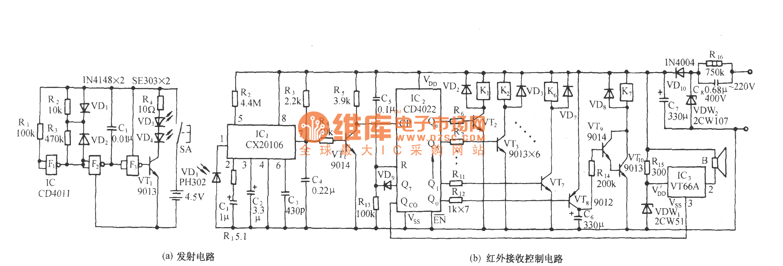
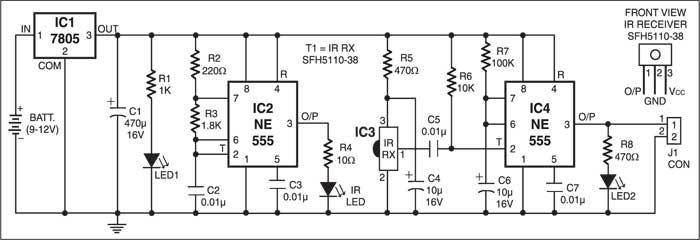
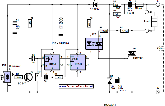
Infrared switch circuit diagram. In this article we will be discussing a very useful and reliable security device called infrared motion detector circuitthe circuit can be used for detection of moving object or body with the use of infrared sensors like ir pir etc. In this circuit the capacitor charge has to reach the logic threshold of the cmos invertor. It can be operated using the tv remote handsetthe load can. Here is the circuit of an ultra sensitive ir receiver that can be used to switch on various. The circuit is an important part of an automatic faucet robot and touchless switch. Ir receiver circuit is very simple we just need to connect a led to the output of the tsop1738 to test the receiver.
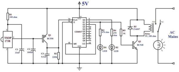
Ir receiver circuit diagram. Circuit diagram of infrared remote control switch. Nowadays security is the first and foremost requirement of everyones life. If you want to operate your home electrical appliances remotely then this ir or infrared remote control switch circuit can be ideal for you. Along with the pir sensors a simple circuit is used with it. We have use bc557 pnp transistor here to reverse the effect of tsop means whenever the output is high led will be off and whenever it detects ir and output is low led will be on.
Ir infrared remote controlled switch circuit diagram for lightfan appliance. In the receiver section there are 3 photodiodes which will detect the infrared signals from the receiver and produce leakage current to the capacitor c1. Infrared switch circuit d mohankumar 04172010. This home made wireless remote controlled switch system is a very easy to construct and can change our living experiance. An above image is an infrared proximity sensor circuit diagram. Tsop1738 is used in the circuit for sensing the infrared signal output from remote.
The main components of this ir remote control switch are ca 3130 operational amplifier and 4018 counter. The circuit is using a 5v relay switch at the output from which you can connect any ac appliance like fan light lamp etc. As the power supply is 5 volts the input threshold is around 36v which takes about 3rcs or about 15 seconds. Sensitive ir switch circuit d mohankumar 12042009. When switch s1 is in on position the transmitter circuit activates to produce a square wave at its output pin 3. Posted in infrared ir ir sensor on 2015 09 22.
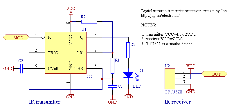
Once reached the inventor triggers the 555 timer and operates the. This current is given to the inverting input of 3130 ic which will get triggered by this current and give amplified output. Ir remote controls switch circuit. The oscillator frequency can be adjusted using preset vr1. The two infrared leds ir led1 and ir led2 connected at its output transmit modulated ir beams at the same frequency 38 khz. Transmitter section and receiver section.
The infrared remote control switch is divided into two sections. The circuit is simple and easy to make it has 2 transistors 4 resistors an ir led an ir phototransistor and a purple or white or green led use as an indicator so you can remove it if you.
