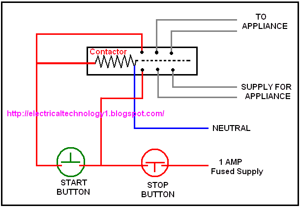
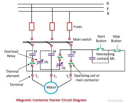
Effectively looking the start button closed. Either of the two start buttons will close the contactor either of the stop buttons will open the contactor.

Magnetic Motor Starter Wiring Diagram War 7 Mareikekirsch De
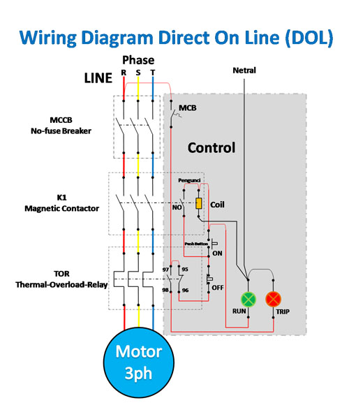
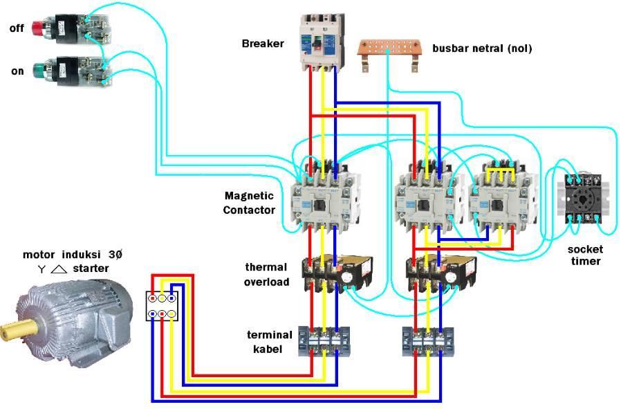
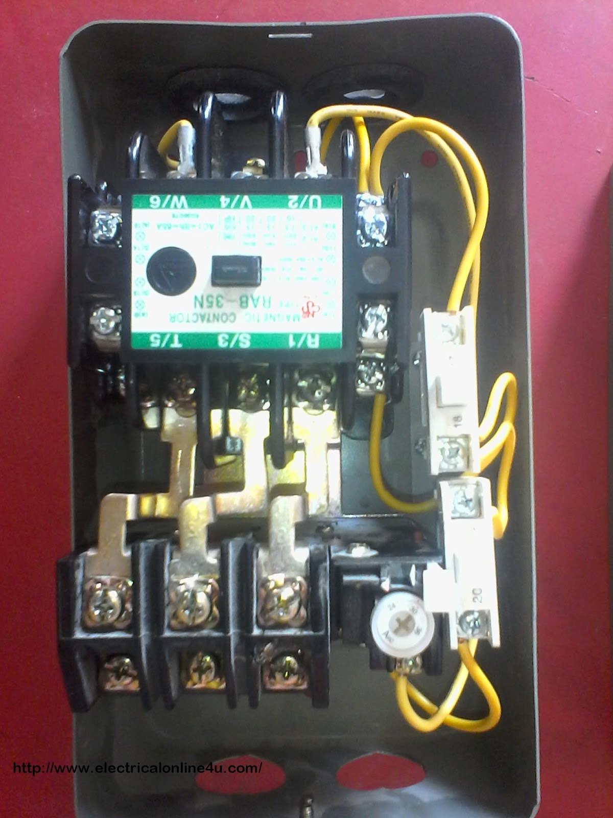
Magnetic contactor circuit diagram. The design of this type of contactor is most advanced among all other types of contactors. Therefore the operation of this contactor is safe compared to manual contactor. 3 phase motor contactor wiring diagram gallery contactor wiring diagram for three phase motor. Usually circuits exceeding two components have two basic types of connections. This is an electromagnetic type contactor and it can operate automatically. The contactor will have space for the red power wires coming in from the photocell circuit breaker and lights.
A simple circuit diagram. This magnetic field pulls the armature into the coil and this creates an electrical arc. Posted on may 9 2018 august 9 2018 by headcontrolsystem. A wiring diagram is a streamlined conventional photographic representation of an. Magnetic contactor circuit diagram luxury thermal overload relay. Electric currents flow in through one contact and into the device in which the contactor is embedded.
Therefore the function of the contactor is to switch an electrical circuit on or off. The current in the magnetic contactor is carried out with the contacts. Note that one one of the contactor acts as a switch for the start button. How to do contactor wiring for 3 phase induction motor with 3 pole circuit breaker overload relay nonc push button switches in this tutorial post i will tell you about motor contactor wiring and its diagram. The above diagram is a complete method of single phase motor wiring with circuit breaker and contactor. Collection of contactor wiring diagram pdf.
How to wire a contactor and. In the above one phase motor wiring i first connect a 2 pole circuit breaker and after that i connect the supply to motor starter and then i do cont actor coil wiring with normally close push button switch and normally open push button switch and in last i do connection between capacitor. The black power wires will need to be tied together externally such as through a wire nut. You must watch. A series circuit is a circuit through which components are connected along a single path hence the current flows through one. A wiring diagram is a simplified conventional pictorial representation of an electric circuit.
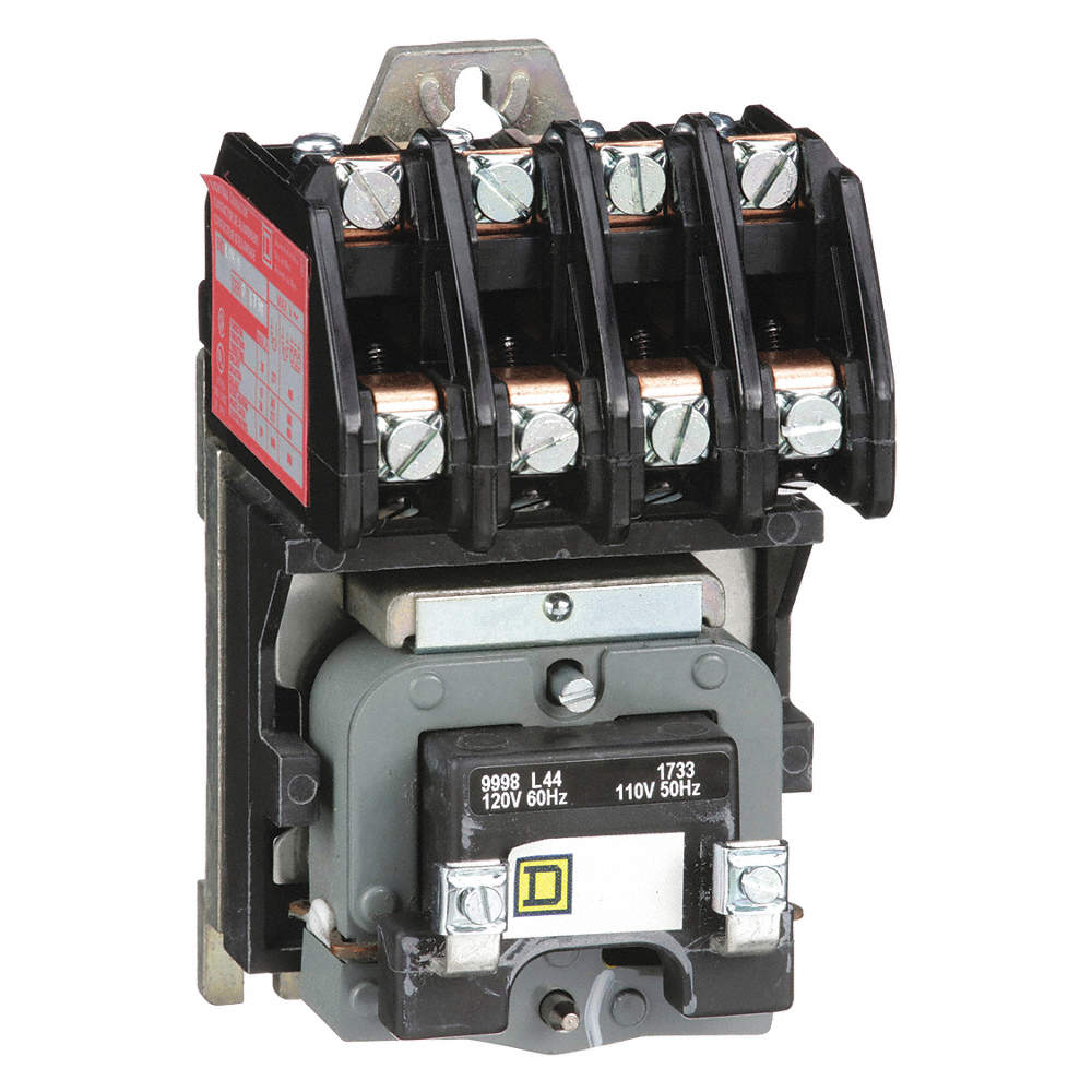
The lights connect to the output ports on the contactor. The contact includes different contacts like power contacts contact springs and auxiliary contacts. The circuit of the magnetic contactor is enclosed in an insulating material like nylon 6 thermosetting plastics and bakelite. Contactor wiring diagram pdf download. It requires a small amount of control circuit to turn on and off the load.


