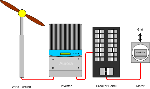
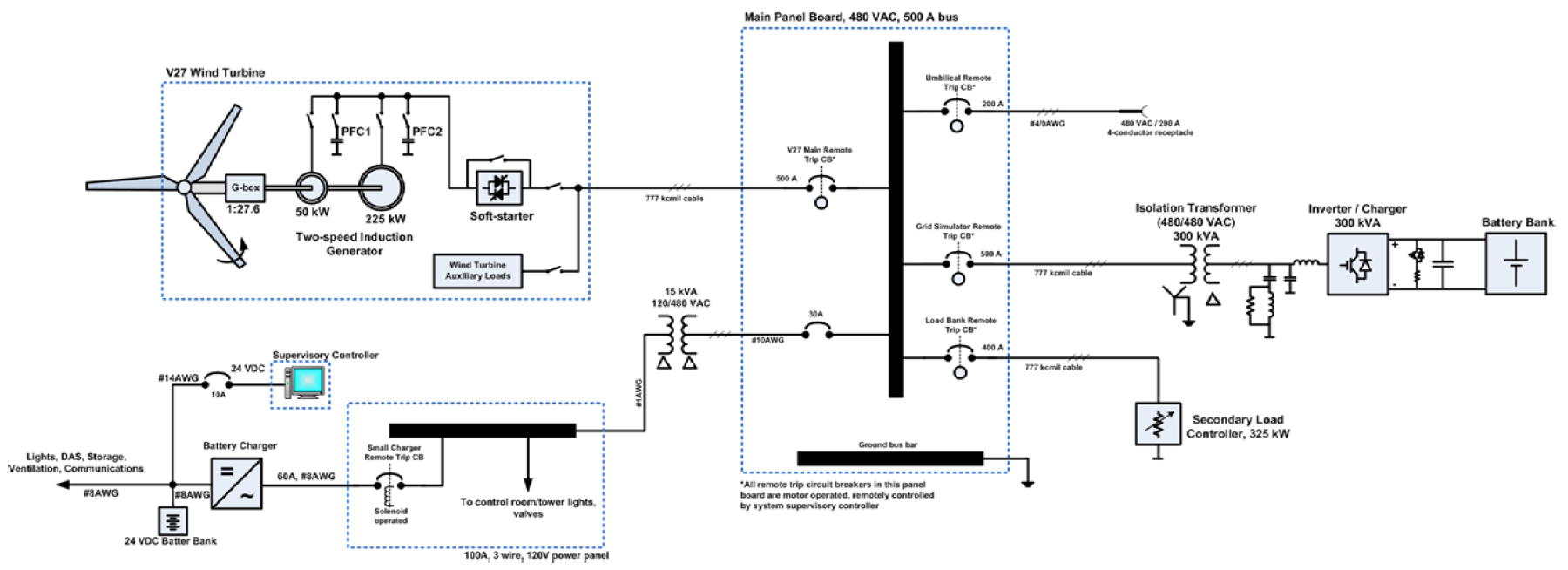
A wiring diagram is a schematic which uses abstract pictorial symbols to demonstrate all the interconnections of components in a system. It shows the elements of the circuit as simplified shapes and also the power and also signal connections between the devices.

Modeling And Simulation Of A 12 Mw Active Stall Constant
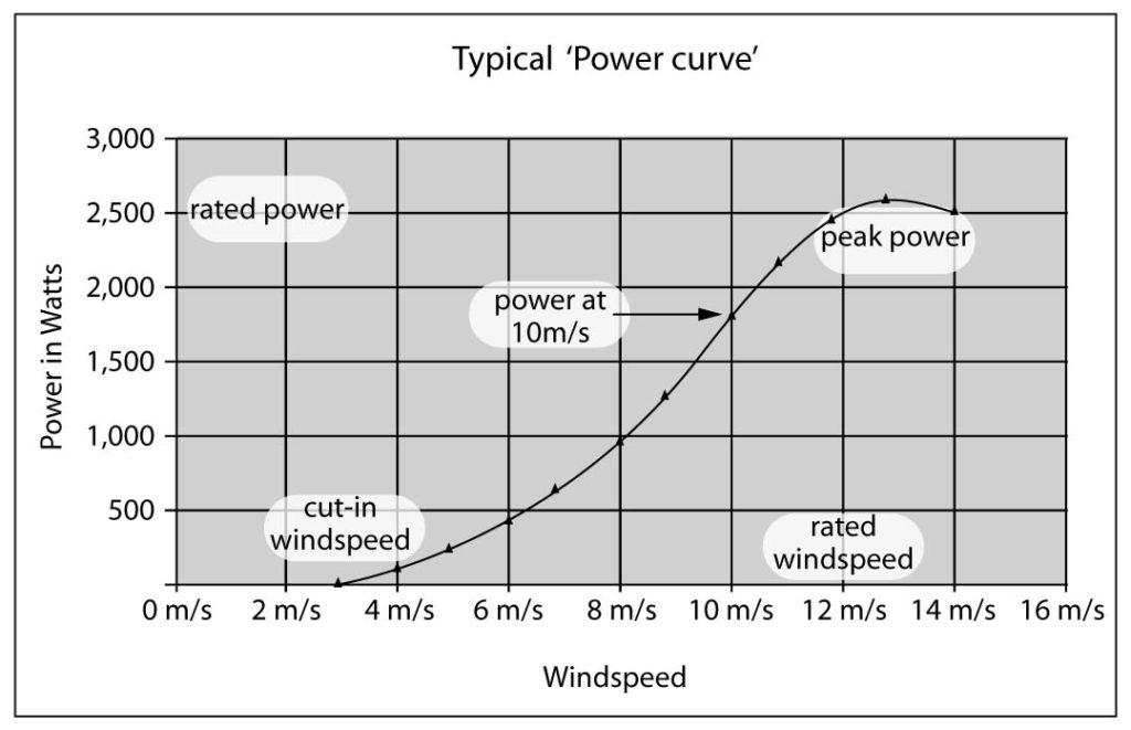
Wind turbine electrical diagram. Wind energy is used to rotate these blades which are mounted at a height of almost 40 meters. The smallest turbines are used for applications such as battery charging for auxiliary power for boats or caravans or to power traffic warning signs. A wind turbine or alternatively referred to as a wind energy converter is a device that converts the winds kinetic energy into electrical energy. Variety of wind turbine wiring diagram. The shaft of the turbine is coupled with an electrical generator. Wind turbines are manufactured in a wide range of vertical and horizontal axis.
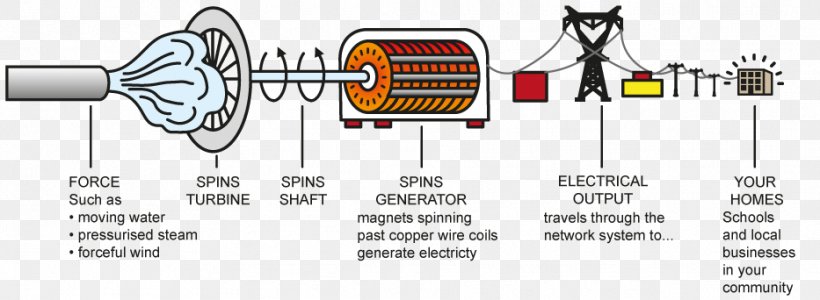
Principle of wind turbine. Learning how a wind turbine works is easy as long as you first make sure to know how a turbine generator works. Wind turbine wiring diagram whats wiring diagram. Symbols that represent the components inside the circuit and lines that represent the connections together. The output of the generator is collected through electric power cables. Nuclear power plant working principle advantages disadvantages with diagram.
Wiring diagrams comprise two things. All the wind turbines used today are horizontal axis machine with 3 bladed rotor spinning in a vertical plane. A wiring diagram is a simplified standard photographic representation of an electrical circuit. When wind strikes on the turbine blades the turbine rotates due to the design and alignment of rotor blades. The diagram of the wind turbine above is a side view of a horizontal axis wind turbine with the turbine blades on the left. Most modern wind turbines are built with a horizontal axis similar to the one seen in the figure.


