A dual starter connects the motor terminals directly to the power supplyhence the motor is subjected to the full voltage of the power supplyconsequently high starting current flows through the motor. In this tutorial we will show the star delta y δ 3 phase induction ac motor starting method by automatic star delta starter with timer with schematic power control and wiring diagram as well as how star delta starter works and their applications with advantages and disadvantages.

Star Delta Motor Starter Explained In Details Eep
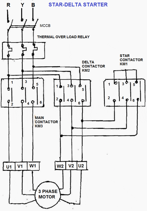
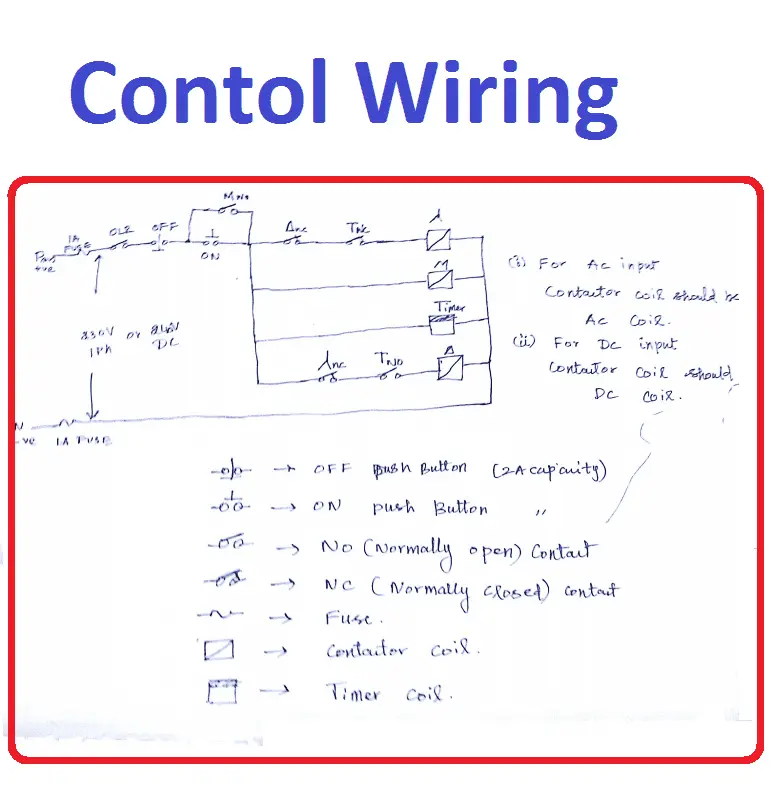
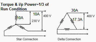
Star delta starter control circuit diagram pdf. The power circuit uses to create contact between the motor and three phase power supply. This is a big advantage of a star delta starter as it typically has around 13 of the inrush current compared to a dol starter. Star delta connection diagram and working principle. The control circuit uses to control the starter circuit such as on off and tripping operations. Here the circuit diagram of star delta starter explained in detailhere you will learn the connection of star delta starter with three phase motorthe power circuit diagram and control circuit diagram of an automatic star delta starter are explained belowlets understand the star delta starter diagram. The most active post in electrical engineering centre blog is star delta starter and star delta motor connectioni received many comments and request for star delta circuit diagram.
Circuit documents 8 19 power supply 8 21 control circuit supply 8 24 contactor markings 8 25 direct on line start of three phase motors 8 26 control circuit devices for direct on line start 8 34 star delta switching of three phase motors 8 35 control circuit devices for star delta starting 8 45 pole changing motors 8 47. Star delta starters consist of a power circuit and control circuit. Refer to the below star delta circuit. This equipmentappliance reduces starting current and starting torque. In the diagram of power circuit of star delta starter u2 and v2 of 3 phase motor should be connect to 4 and 6 respectively instead of u2 and v2 are connected to 6 and 4 of delta contector km2. Automatic star delta starter design normally consists of three contactors an overload relay or circuit breaker and a timer for setting the time in the star position starting.
The on delay timer diagram is also shown in the diagram. A 8 pin timer are used. So this time i want share my simple star delta circuit diagram completed with power and control line circuiti hope it can be as basic reference for all electrician about star delta starter diagram. Star delta connection circuit diagram. Star delta starter control circuit diagram. There is minor correction is require to change printed in boxes sequence of 3 phase wires from w2 v2 u2 to w2 u2 v2 to get delta connection properly.
In the above star delta starter control circuit wiring diagram with timer and normally close push buttonnormally open push button switch. This type of starting is suitable for small motors below 5 hp 375 kw. A star delta starter is a type of reduced voltage starterwe use it to reduce the starting current of the motor without using any external device or apparatus. In control wiring diagram all magnetic contactors coils are rated 220 vac.


