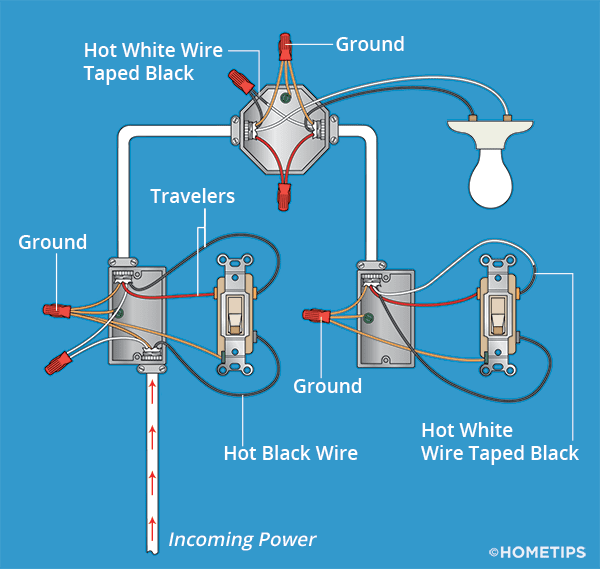
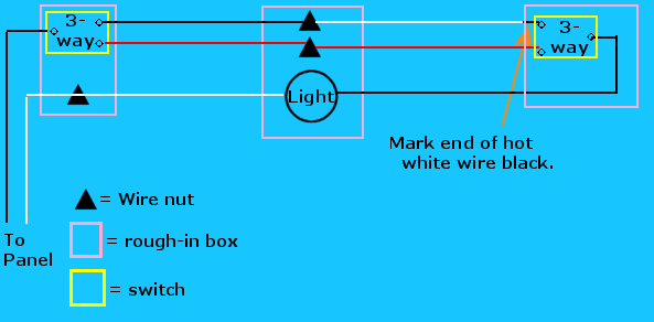
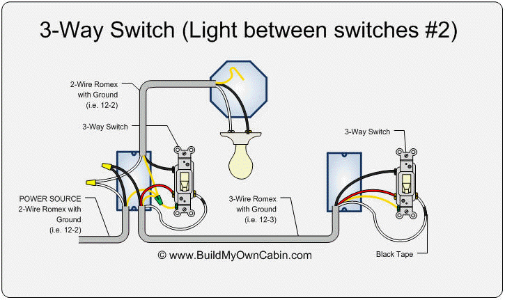
The steps above describe installing a 3 way switch and provide a 3 way switch diagram utilizing one light fixture. This 3 way switch wiring diagram shows how to wire the switches and the light when the power is coming to the light switch.
3 Way Switch Troubleshooting Diy
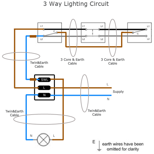
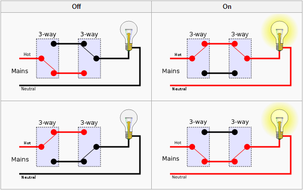
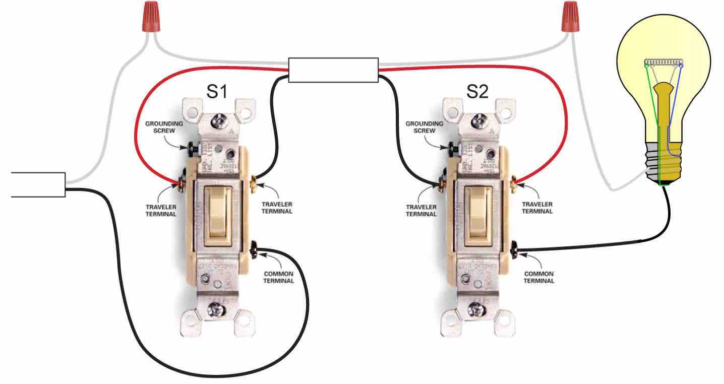
Three way light circuit diagram. In the above 3 way switch wiring diagram at each switch the black wire gets connected to the copper or black screw. Three wires between the two end switches probably using 3 core and earth cable. If you intend to add multiple lights with a 3 way switch use the 3 way switch for multiple lights diagram. A three way switch is fundamentally different in its operation from a regular two way switch. The goal is to place two switches at separate locations which control the exact same device. The two hot wires of three wire cable connect to a pair of brass colored traveler terminals on each switch.
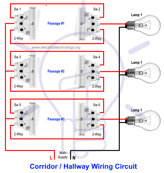
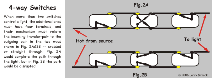
All three switches are connected together by a three core and earth control cable. Wiring diagram 3 way switch with light at the end in this diagram the electrical source is at the first switch and the light is located at the end of the circuit. Usually the third wire passes the middle intermediate switch but is joined in a separate terminal block. Three way switching 3 wires. Take a closer look at a 3 way switch wiring diagram. In the ceiling light fixture electrical box one black wire from a 3 way switch gets connected to the black load wire on the light fixture.
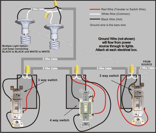
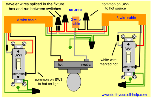
Three wire cable runs between the switches and 2 wire cable runs to the light. With these diagrams below it will take the guess work out of wiring. You must completely forget about the notion of a switch being a simple openclosed circuit and look at the diagram of the circuitry of this modern alternative. This 3 way light switch diagram shows connections when the power comes into the first switch on to the second switch and then on to two or more lights switched by the 3 way circuit. Interested in a 4 way switch wiring diagram. No longer allowed after 2011 nec if no neutral wire in switch boxes 3 way switch wiring diagram light fixture between switchesline voltage enters the first 3 way switch outlet box light fixture is located between switch boxesno longer allowed after 2011 nec if no neutral wire in switch boxes.
3 way switch wiring diagram line to light fixtureline voltage enters the light fixture outlet box. The black and red wires between sw1 and sw2 are connected to the traveler terminals. 3 way switch wiring diagram depicting all wires in the ceiling junction box. In this diagram the incoming hot wire attaches to the first switchs common dark colored terminal. This might seem intimidating but it does not have to be. This is also known as the conversion method since it is the easiest way to add a second light switch to an existing circuit.
Pick the diagram that is most like the scenario you are in and see if you can wire your switch. Three way switching schematic wiring diagram the circuit consists of a two way switch at each end top and bottom switches in fig 2 and an intermediate switch in the middle. Wiring multiple lights on a 3 way switch.
