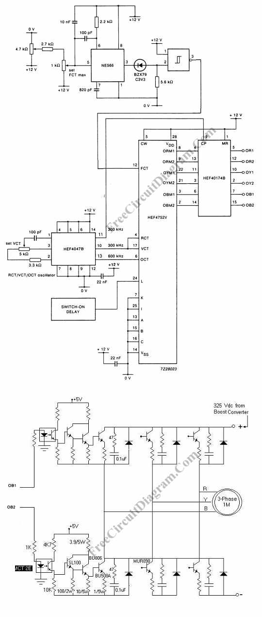
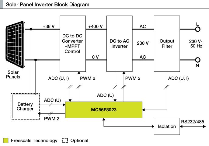
Please careful with this circuit because high a voltage. Three phase inverters require microcontroller design where the timings of the all three phases need to be precisely timed and executed.
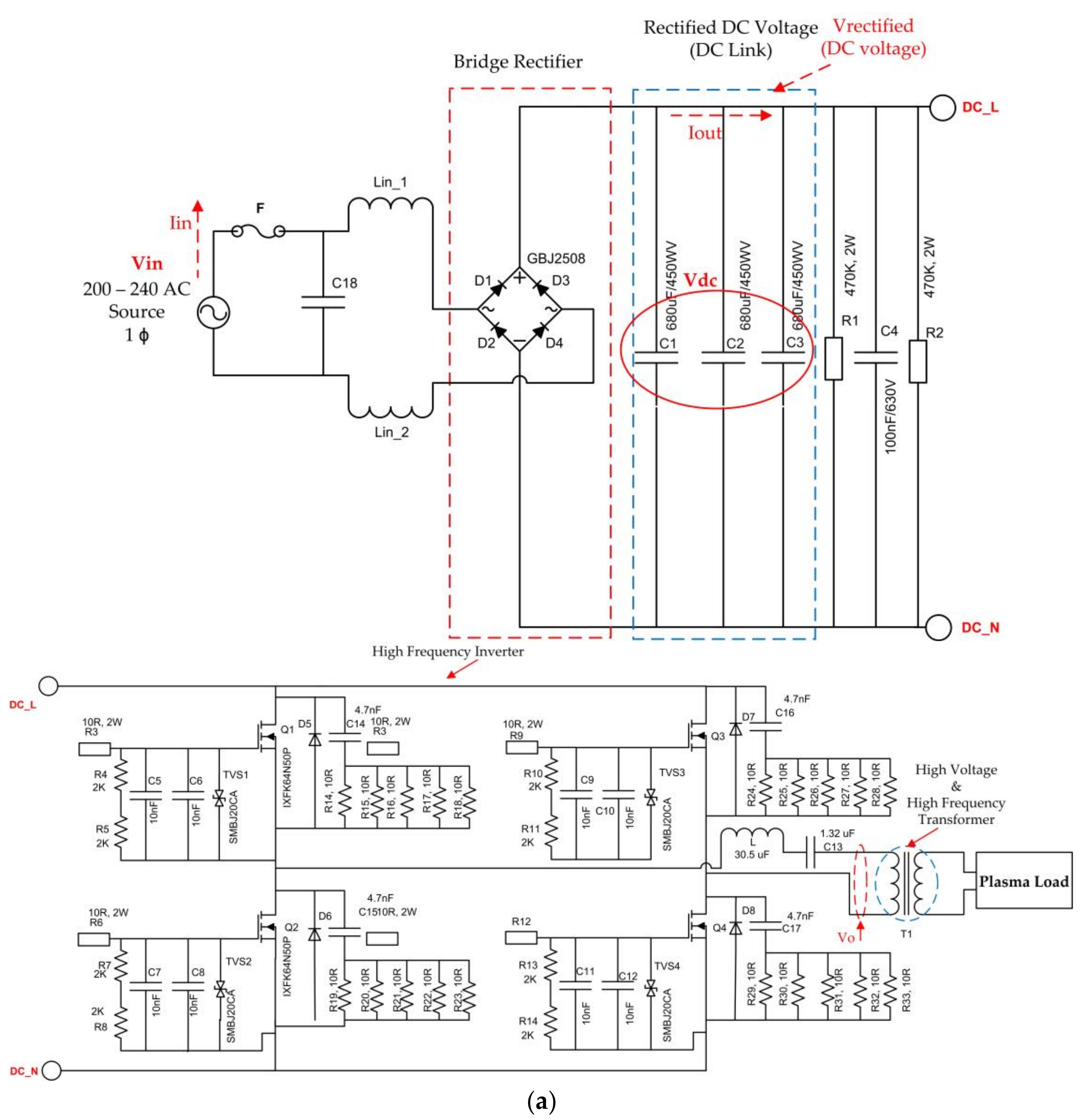
Electronics Free Full Text 4t Analog Mos Control High
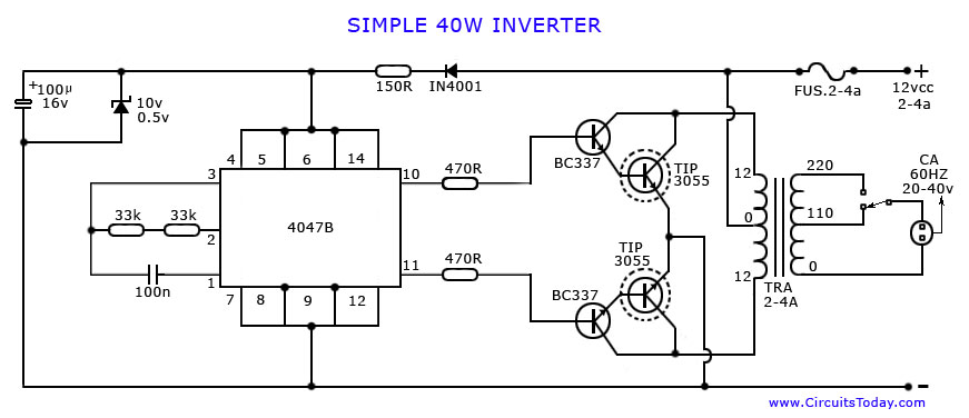
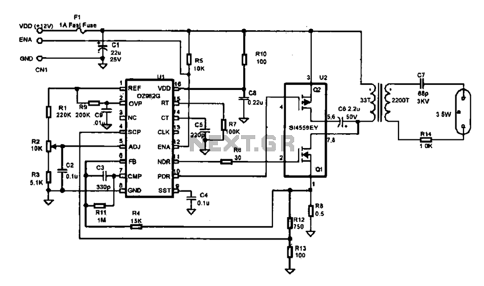
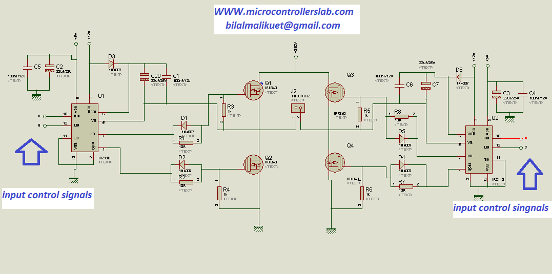
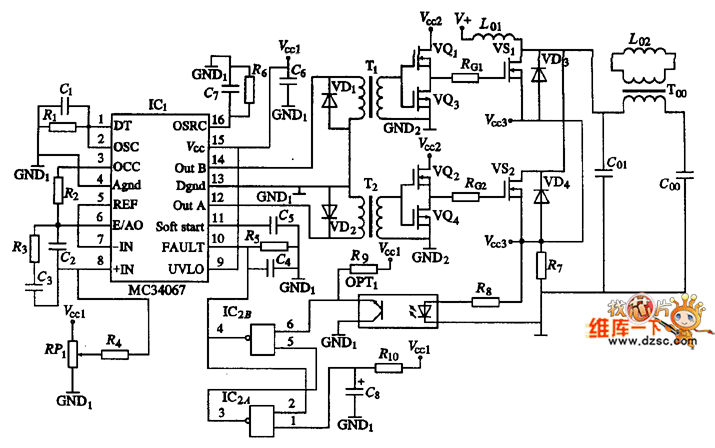
Inverter control circuit diagram. The spwm accuracy of eg8010 was not high enough waveform so the inverter output was not good enough as pure sine wave. The circuit diagram for an inverter connection at home is given below. Simple pwm inverter circuit using sg3524. 12 volt dc to 120 volt ac inverter 1 to1000 1 kw watts. Car stereo wiring. The circuit diagram of the current source inverter with r load is shown in the below figure.
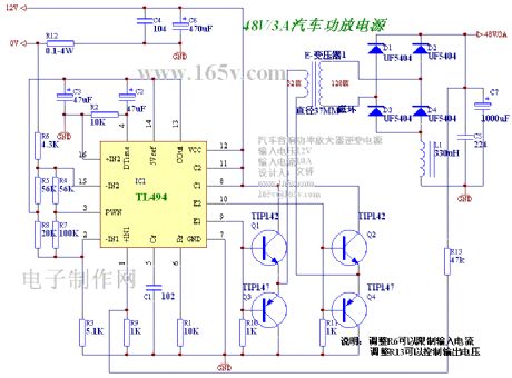
Build this with our guidance. Related electrical wiring tutorial. Few days ago gohz made a 24v 2000w power inverter in home sharing some design schematics and circuit diagrams. The dead zone time was a bit. This is the circuit diagram of 2000w high power inverter circuit. Ups inverter wiring diagram with auto manual changeover switch system.
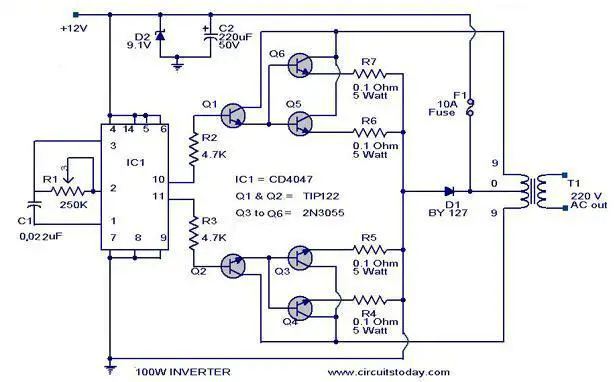
The inverter provide the power output upto 500 watts. Use 24v dc supply for operation and connect 24v 5a or more than 5a transformer. Current source inverter with r load the circuit consists of four thyristor switches t 1 t 2 t 3 t 4 i s is the input source current which is constant and you can see that there is no any anti parallel diode is connected. According to the below circuit diagram you can see that during load shedding light 3 fan and tv can be run by the inverter. Simple high frequency inverter circuit diagram with free pcb layout. According to your requirement connect the load to the inverter.
This pwm inverter circuit has 12v input 220v output and 250 watt output power. 12 volt automotive inverter circuit. Now according to the below ups connection diagram connect an extra wire phase to those appliances where we have already connected phase and neutral wires from power house db ie two wire as phase live as shown in the below fig. Click on image for best resolution. This is based on the mosfet3205. Timer generator oscilator computer.
Output power can be extended. The picture was taken in short circuited. The internet is flooded with single phase inverter circuit diagrams but there are only few circuit diagrams of 3 phase inverter out there a simplest possible 3 phase inverter is described here. 2000w inverter circuit diagram.


