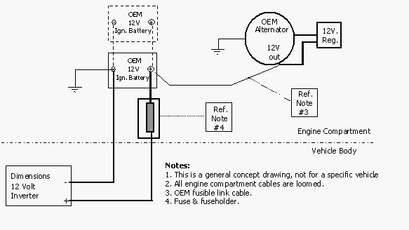
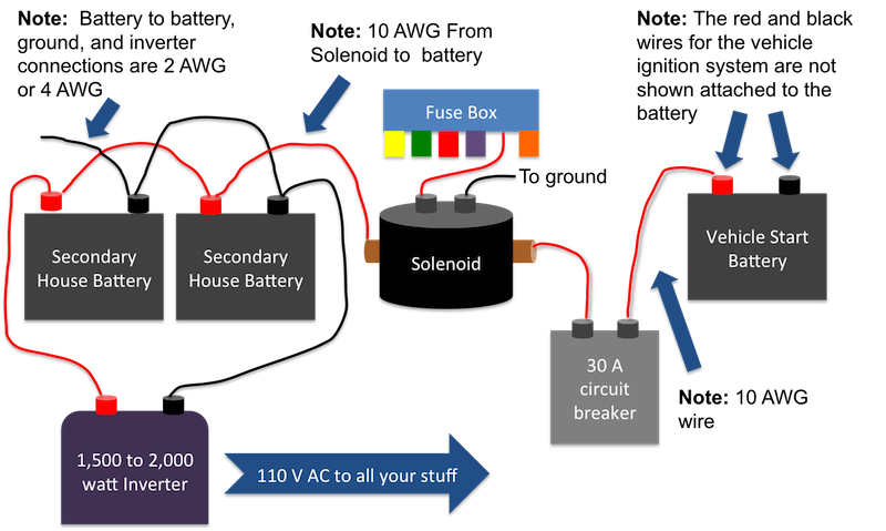
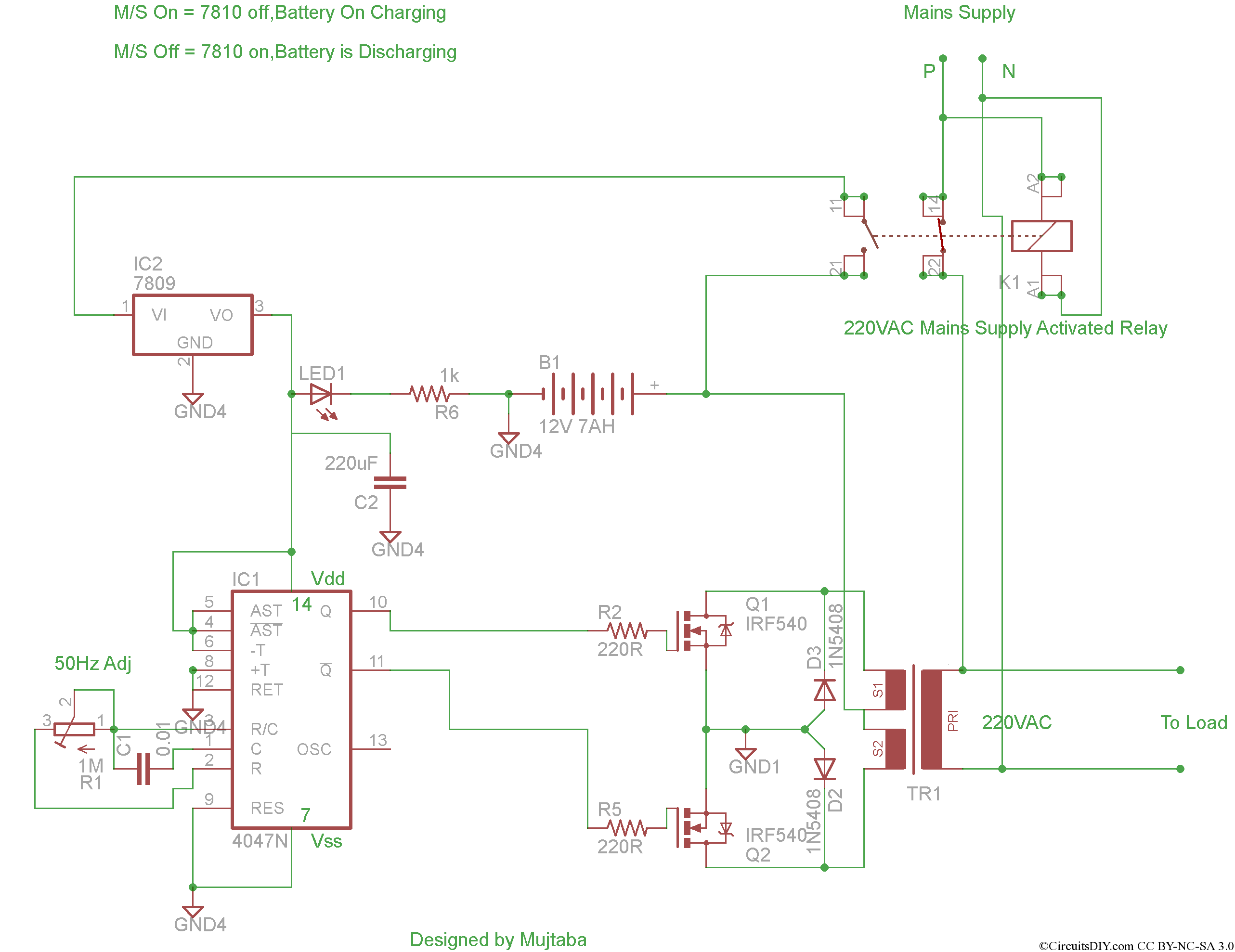
The inverter capable to handle loads up to 1000w its depended on your power inverter transformer. Ups inverter wiring diagram with auto manual changeover switch system.

I P S Circuit Diagram Generator 2 Brillenstudio Weichert De
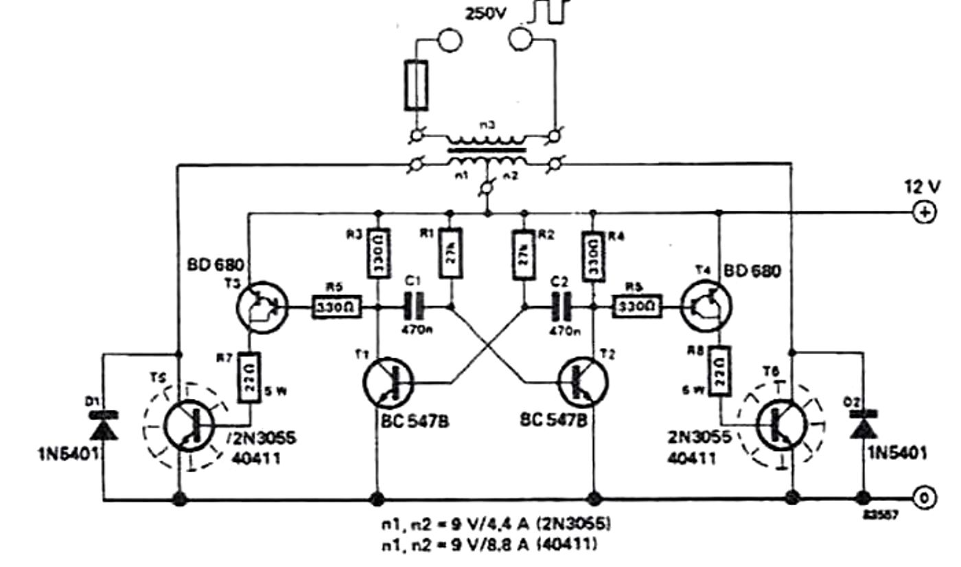
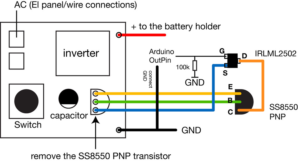
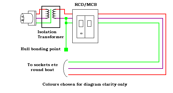
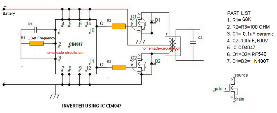
Inverter wiring circuit diagram. Generally circuits with greater than 2 parts have two standard sorts of links. Rv inverter charger wiring diagram collections of rv inverter charger wiring diagram unique wiring diagram for rv. It carries out the key role of providing square waves to the inverter division. Heatsink is required for cooling the mosfets. It reveals the elements of the circuit as streamlined shapes and also the power as well as signal connections in between the gadgets. According to the below circuit diagram you can see that during load shedding light 3 fan and tv can be run by the inverter.
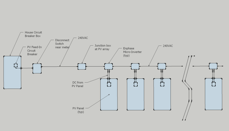
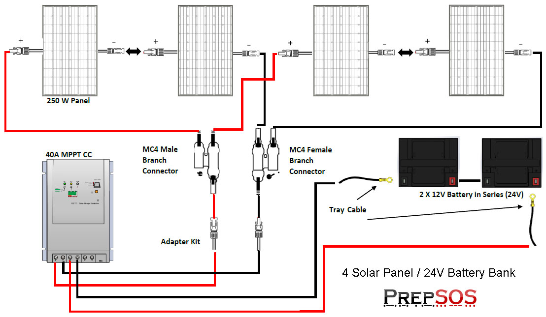
Solar inverter circuit diagram. Please careful with this circuit because high a voltage. The circuit diagram for an inverter connection at home is given below. A wiring diagram is a simplified traditional photographic depiction of an electrical circuit. 1000w power inverter circuit diagram. N1 n2 gates of ic 4049 are employed as an oscillator.
A collection circuit is a circuit where components are attached along a solitary path so the. Variety of inverter generator wiring diagram. 2000w inverter circuit diagram. This power inverter is sensitive in short circuit protection after more than 100 times short circuit tests power on short circuit no load short circuit full load short circuit loading short circuit the power inverter is still work good. Use 24v dc supply for operation and connect 24v 5a or more than 5a transformer. Related electrical wiring tutorial.
Rv inverter wiring diagram. To understand well how to construct a solar inverter it is vital to study how the circuit operates through with the help of following steps. This is based on the mosfet3205. Now according to the below ups connection diagram connect an extra wire phase to those appliances where we have already connected phase and neutral wires from power house db ie two wire as phase live as shown in the below fig. The output terminals of the inverter and the tweezers were scarred. According to your requirement connect the load to the inverter.
The rfp50n06 fets are rated at 50 amps and 60 volts. Click on image for best resolution. This is the circuit diagram of 2000w high power inverter circuit. This inverter circuit diagram which can change the voltage 12 volt dc to 230 volt acscheme inverter circuit is capable of removing power output up to 3000 watt for beginners as possible to assemble a circuit schematic this inverter will be a little complicated and confused but if it succeeds in assembling or assemble it certainly results will be comparable to what we have done and probably. This is the power inverter circuit based mosfet rfp50n06.
