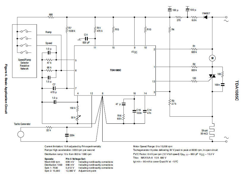
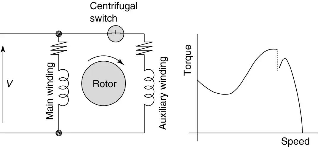
If the volt ages are different it is called separate control. When the voltage of the control and power circuits is the same it is referred to as common control.
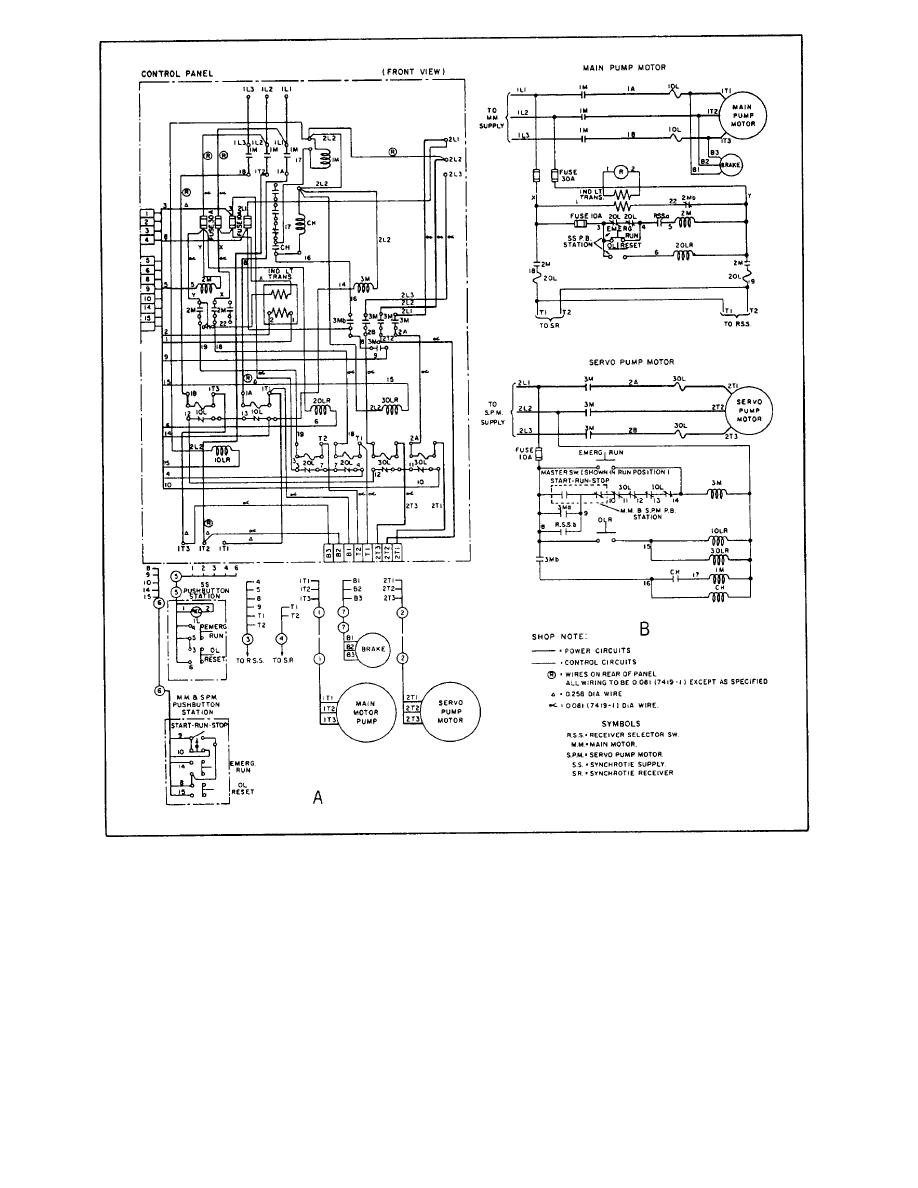
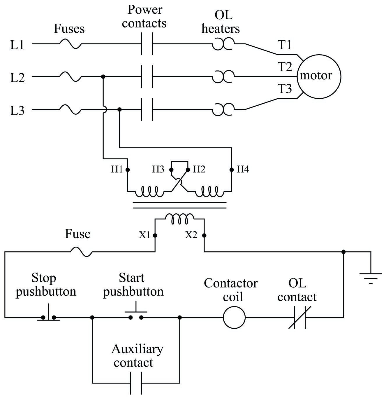
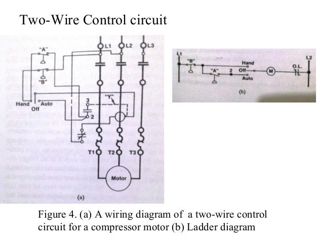
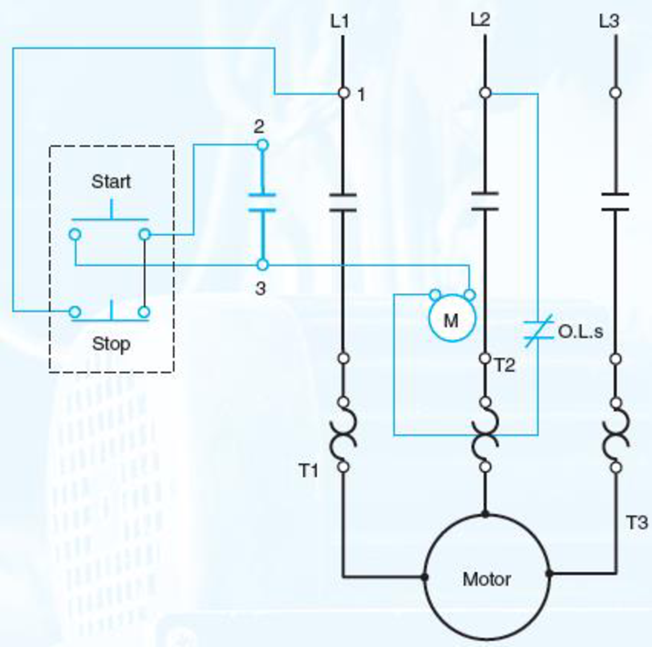
Figure 3 11 Main Motor Controller A Wiring Diagram B
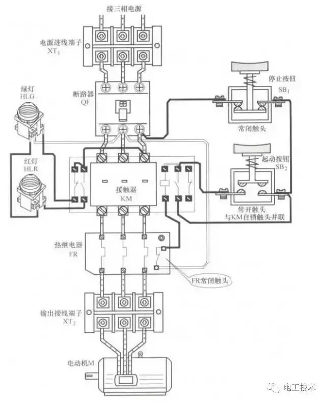
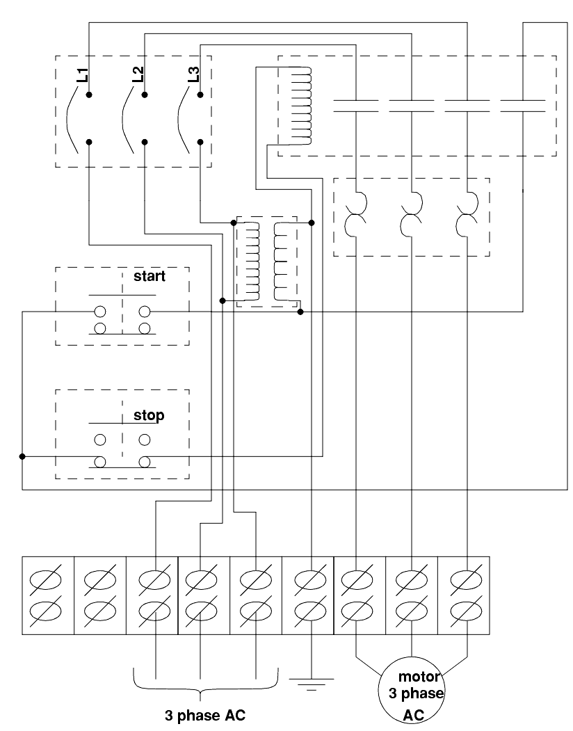
Wiring diagram for motor control circuit. Wiring diagrams show the connections to the controller. Wiring diagrams sometimes called main or construction diagrams show the actual connection points for the wires to the components and terminals of the controller. How to connect a portable generator to home supply system three methods. Multi speed 3 phase motor 3 speeds 1 direction power control diagrams. One line diagram of simple contactor circuit. The fuse is connected in series with both the control circuit and the motor.
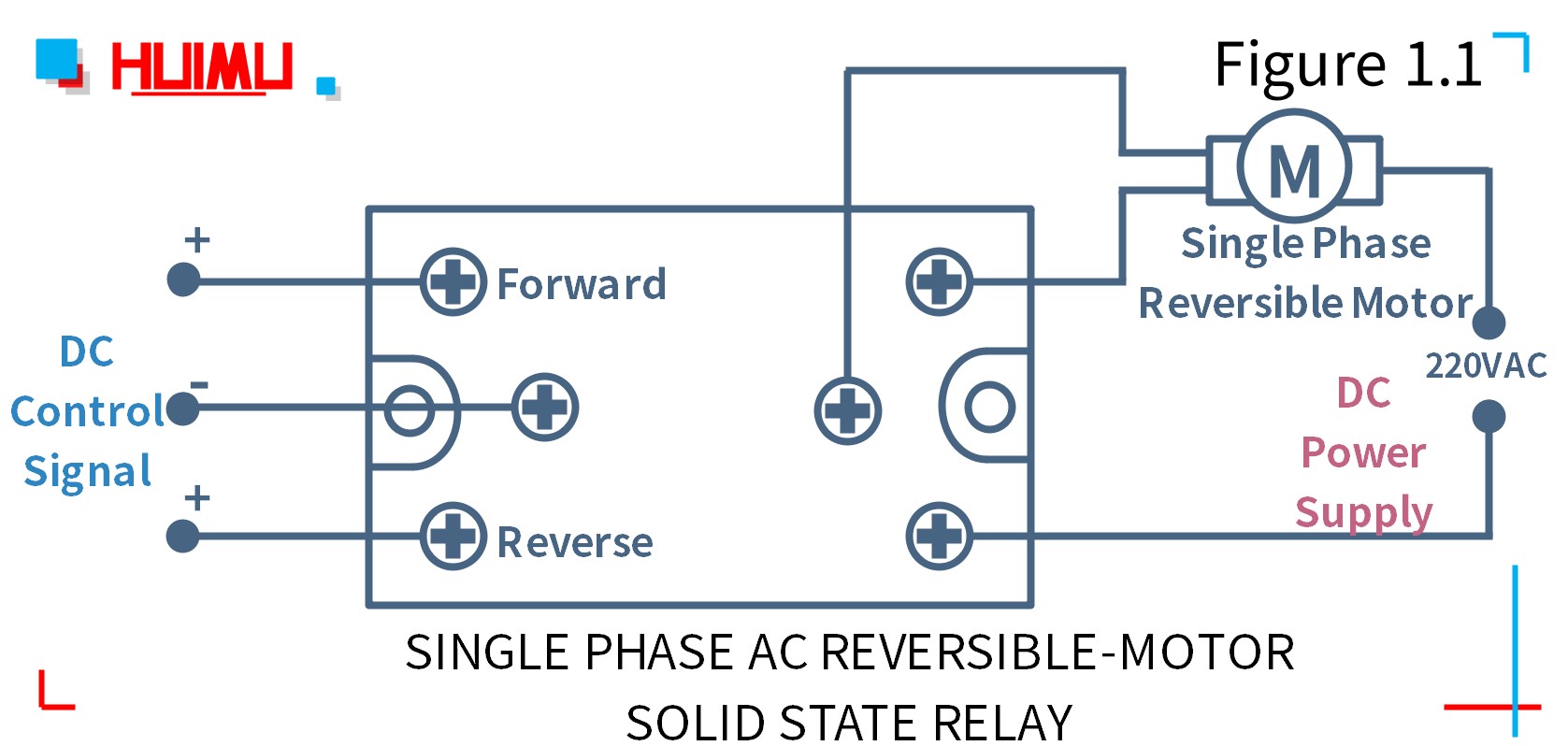
Here i showed the forward reverse wiring diagram. In the diagram i connect the incoming three phase supply l1 l2 l3 to the mccb circuit breaker molded case circuit breaker. Forward reverse motor control diagram for three phase motor for three phase motor forward reverse control circuit. In this particular case i show a low voltage control circuit and a 3 phase higher voltage motor. Feb 5 2020 explore elects agass board electrical diagram on pinterest. The control circuit may not be at the same voltage as the power circuit.
See more ideas about electrical diagram electrical circuit diagram electrical engineering. Wiring diagram parts list design worksheet duration. Basic wiring for motor control technical data. Two speeds two directions multispeed 3 phase motor power control diagrams. This video gives a brief explanation on how a three phase motor control circuit works. Most onoff motor control circuits in the united states are some variation on this wiring theme if not identical to it.
Three phase electrical wiring installation in home iec nec. The control circuit is separate from the motor circuit. I describe each of the components involved such as the motor starter overload start pushbutton stop pushbutton and control power and. A wiring diagram for the start stop pushbutton circuit is shown in figure 917. Typical starter wiring diagram three phase. We use 2 magnetic contactors as forward reverse switch.
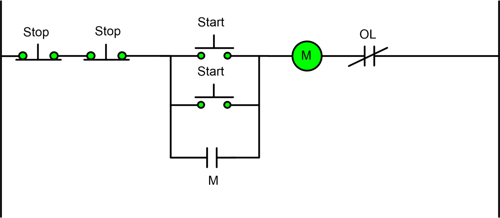
In this video i demonstrate a 3 wire startstop circuit. A very common form of latch circuit is the simple start stop relay circuit used for motor controls whereby a pair of momentary contact pushbutton switches control the operation of an electric motor. If the fuse should open it has the effect of disconnecting power from the line. A simple ladder diagram showing the interconnections of all components in this motor control circuit makes this system easier to understand.
Gallery of Wiring Diagram For Motor Control Circuit