Then the important bit. The follow up question of how we may make the motor stop running is a.
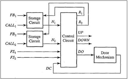
Problem Assignment An Elevator Controller Design Chegg Com
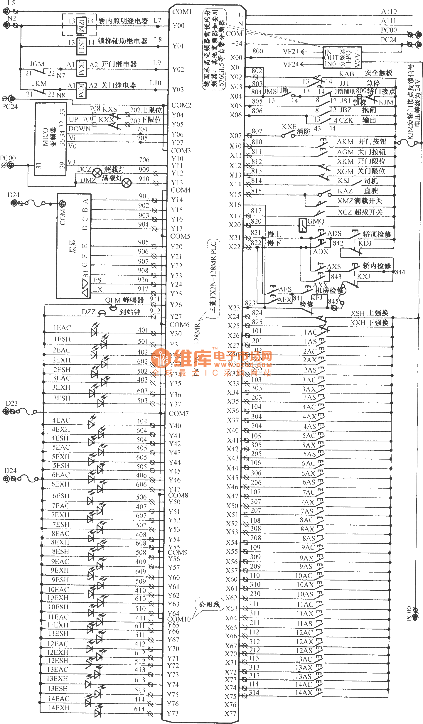
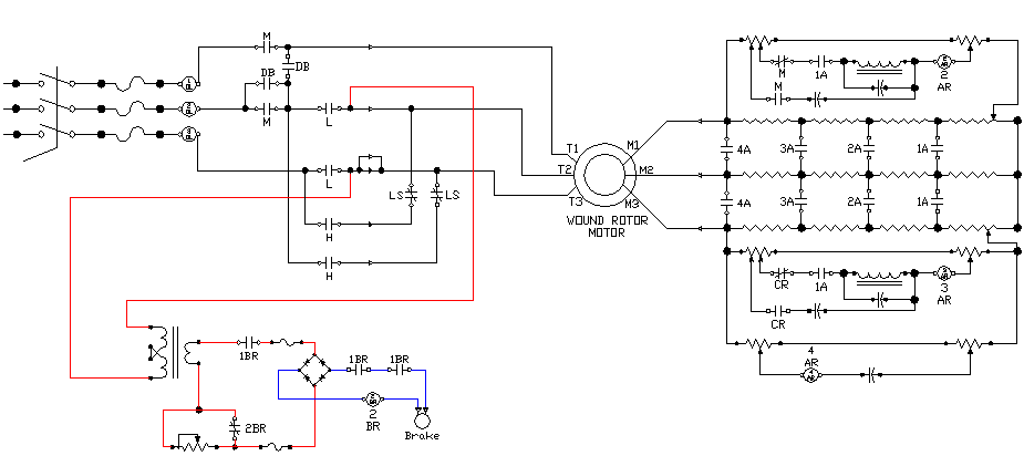
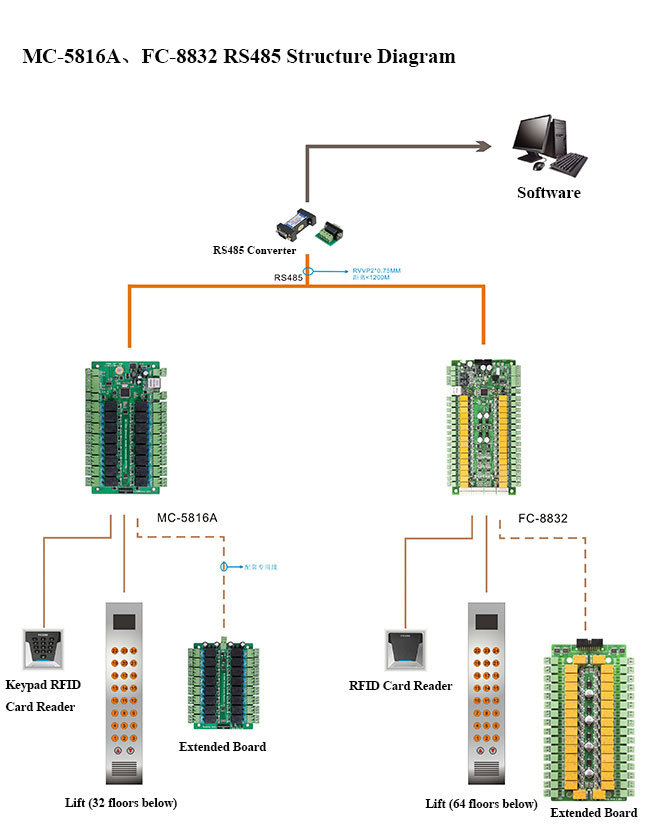
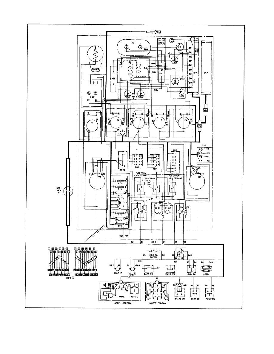
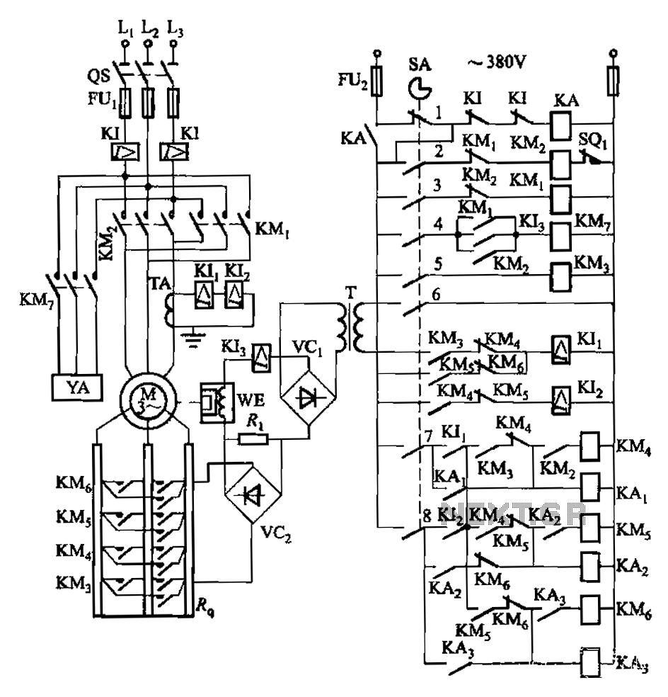
Lift control circuit diagram. Boat lift switch wiring diagram. Elevator control system is the system responsible for coordinating all aspects of elevator service such as travel speed and accelerating decelerating door opening speed and delay leveling and hall lantern signals. How does elevator works circuit diagram types march 29 2019 by dave leave a comment due to the improved control structures hardware and other automation systems in traction elevator systems most of the manufacturers are producing energy efficient elevators. In this approach all the functional and memory are concentrated in the. Each state is a box. Button signals and produces outputs elevator cars moving doors opening etc.
In this remote controlled switch circuit we are using tv remote to onoff the ac light by pressing any button of remote and using the tsop1738 at receiver end. We have used ic 4017 to convert it into a push on push off switch. Draw arrows showing how the system moves between states. It accepts inputs eg. The contact in parallel with the run switch is often referred to as a seal in contact because it seals the momentary condition of the run switch closure after that switch is de actuated. On huge tasks symbols might be numbered to reveal for example the panel board as well as circuit to which the gadget connects and also to determine which of a number of sorts of component are to be.
Boat lift motor wiring diagram sample instructions. For computer laptop. In the design procedure of the elevator control circuit the controller datapath approach was used. Draw a state diagram. Boat hoist wiring auto electrical wiring diagram. Probably another 6 for the lift travelling between floors up and down.
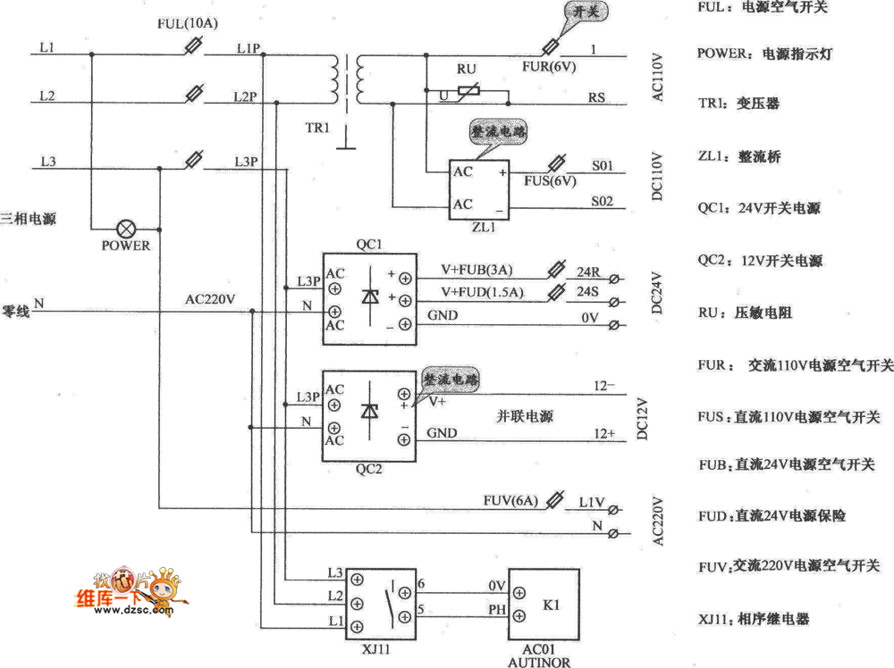
Each state has a fixed output condition which is shown inside the box. Lets start with the most basic float switch. The cylinder is connected to a fluid pumping system. This circuit is known as a latching circuit because it latches in the on state after a momentary action. The elevator works by a three phase power circuit which supplies the motor and a low voltage control. Youtube me channel name khatu shyam plc program and shyam plc program all video used in my channel.
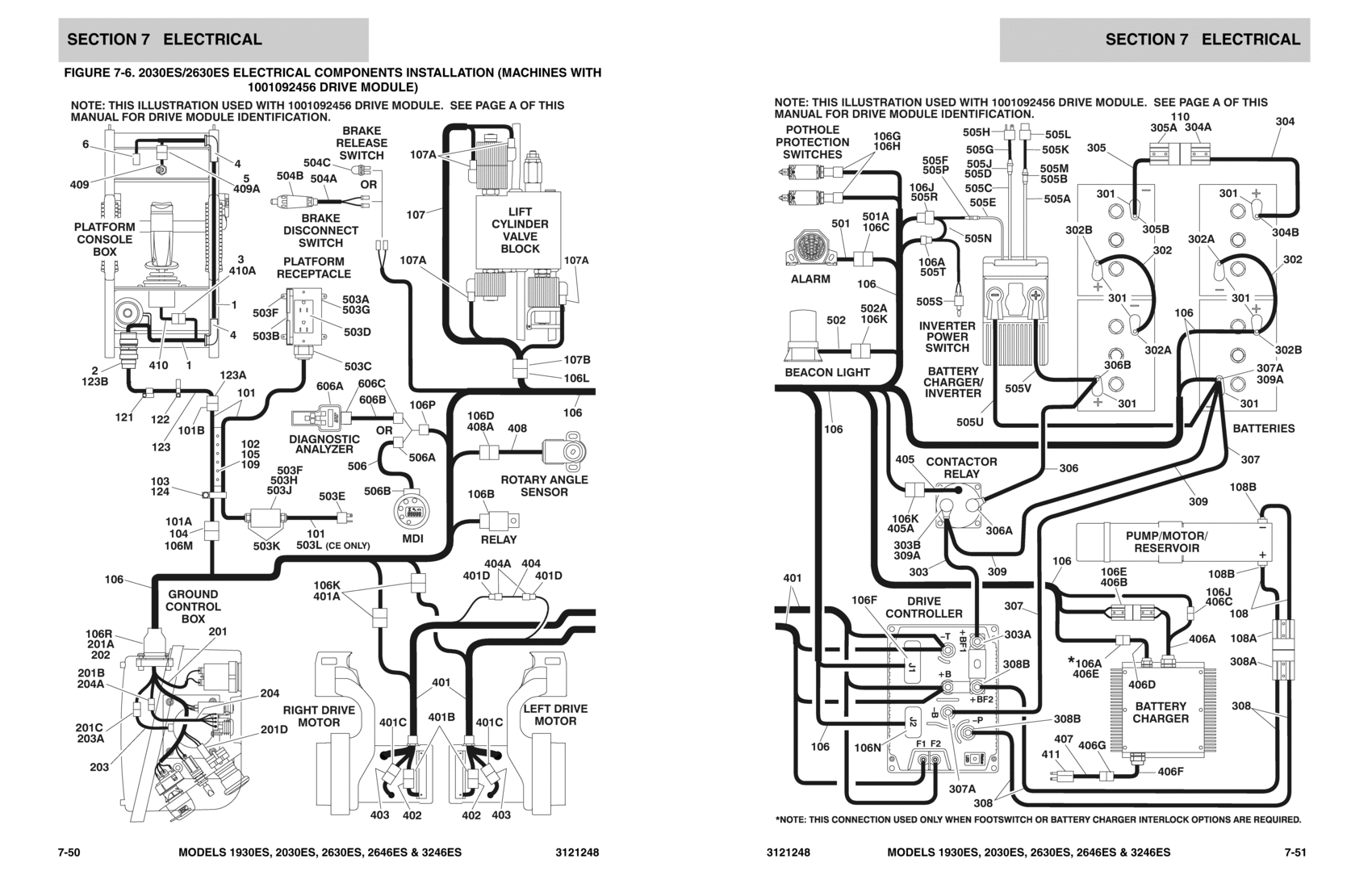
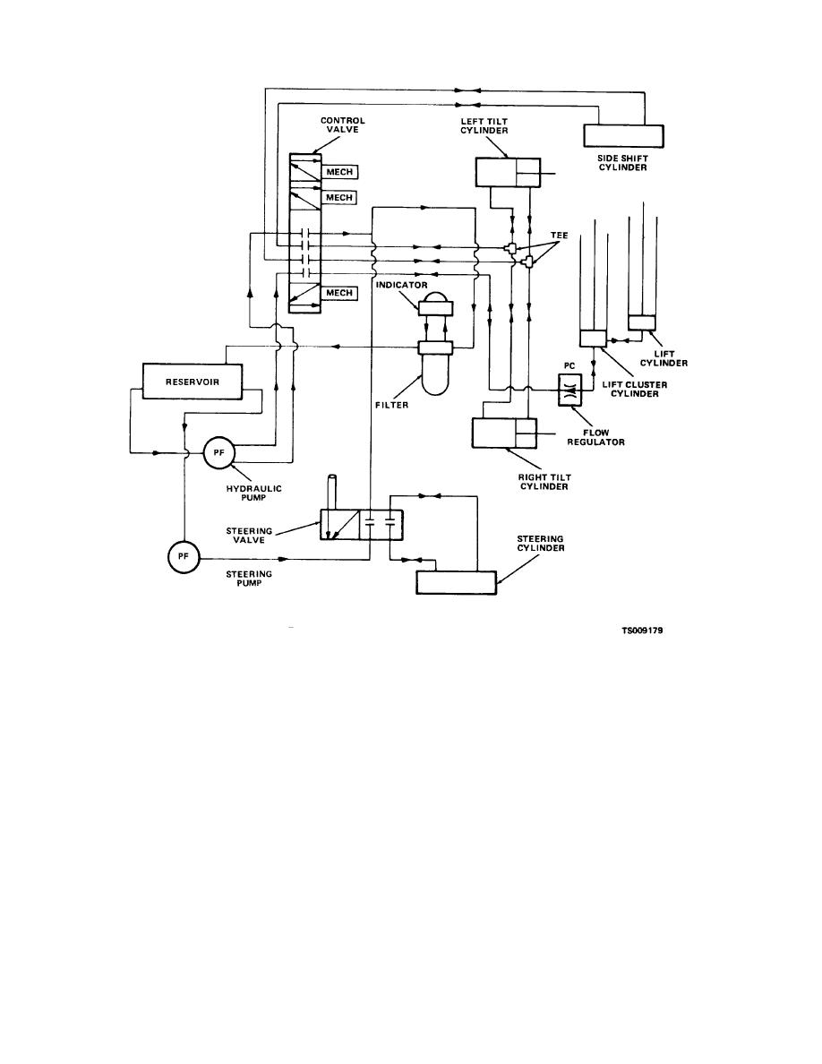
A two wire single pole single throw float switchthe rising action of the float can either close ie turn on a normally open circuit or it can open turn off a normally closed circuitinstallation scenarios might include a normally open float switch turning on a pump to empty a tank control schematic 2 or a normally closed. How to use in this video lift power and control wiring this video. 3 for the lift stationary at each floor. They are designed to lift a car using a hydraulic ram using a fluid driven piston mounted inside a cylinder. This video shows a relay logic elevator circuit diagram and how relays work in slow motion. Receiver circuit is connected to ac appliance via relay so that we can control the light remotely.
