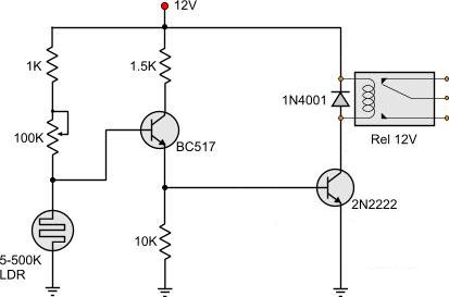
Automatic light operated switch circuit using ldrtriacoptocoupler without relay. Use a 1n4001 or better.

How To Build Dark Activated Led Or Lamp Flasher Circuit Diagram
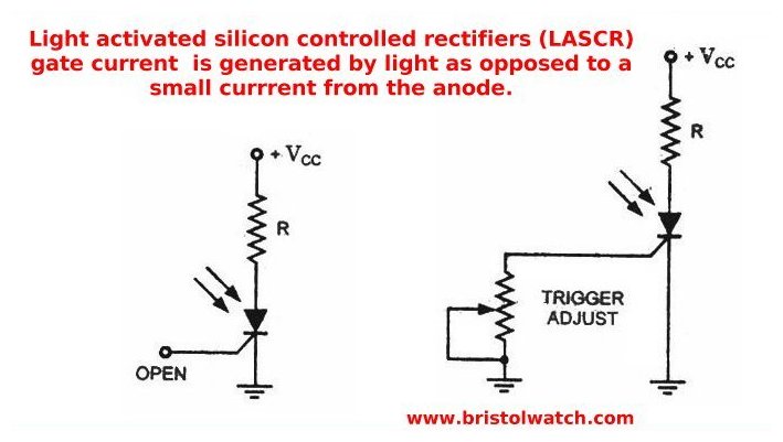
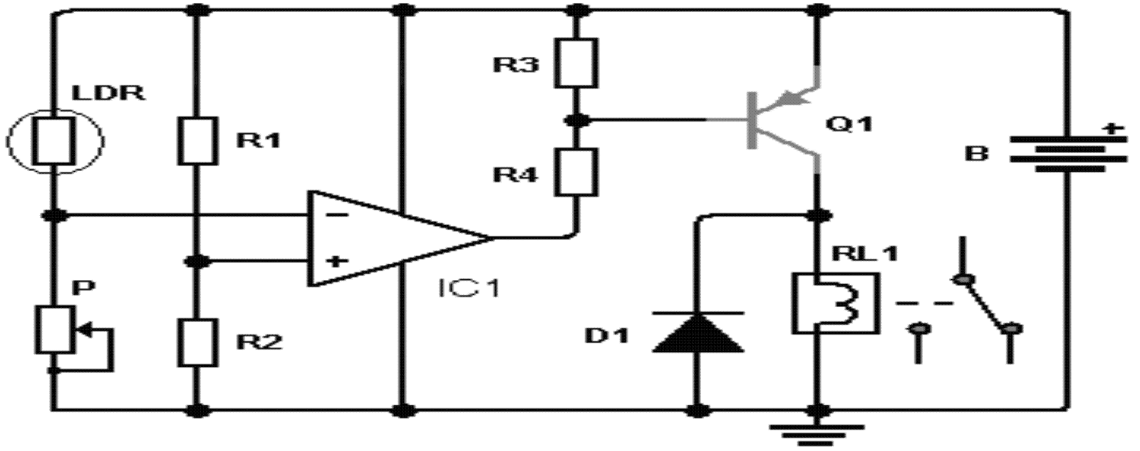
Light activated switch circuit diagram. A simple light activated switch description. This light activated relay circuit presented here uses the 555 timer ic and a light dependent resistor or ldr to form a light sensitive relay in an intruder alarm system or for switching on a lamp at sun set and off at sun rise. At night time all leds glow and in daytime when light falls on ldr all leds switch off automaticallyproject of light activated switch circuit diagram using transistor. Light activated switch circuit mini project. The circuit is based on a voltage comparator circuit wired around ic 1the non inverting in put of ic1 is given with a reference voltage of 6v using resistors r3 and r4. Light activated switch circuit light activating and deactivating switches are simple to build when you are provided with a ldr sensing element and 555 switch activator.
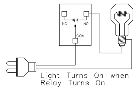
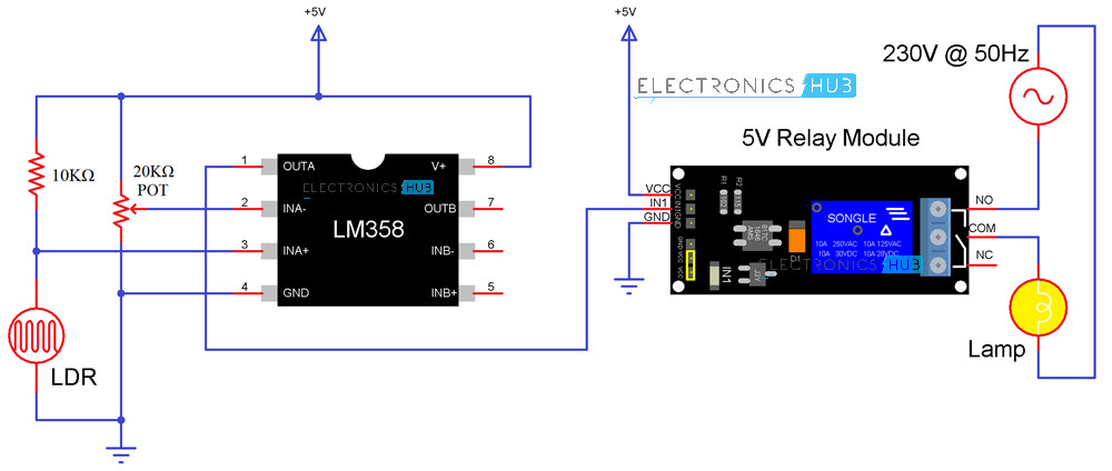
The circuit can activate any ac or dc device connected with the relay when light falls on the ldr. The potensiometer adjust the trigger on level. This is the circuit diagram of a light activated switch based on national semiconductors comparator ic lm 311 and a ldr. This is dark sensitive and light activated switch circuit in this circuit ldr light dependent resistor is used to sensing the light and darkness. The comparator ic lm358 and the ldr. This circuit is simple compared to other light sensitive switching circuits it switches a relay so that you can switch electrical appliances also with it you can use the circuit for garden lamps or outdoor or indoor lighting.
The lm358 ic has 8 pins and can have supply voltages ranging from 3 32 volts. The diode in the circuit diagram shows to be 1n914. It has two internally frequency compensated operational amplifiers. This is a simple and efficient circuit of a light sensor switch or light activated relay switch circuit using a 555 timer ic. The light activated switch circuit mainly consists of two components. The first diagram shows how the circuit can be configured using transistors the second and the third circuits demonstare the principle by using cmos ics while the last circuit explaines the same concept being implemented using the ubiquitous ic 555.
It contains a 10k va. These kind of sensor circuits are widely employed in many applications and may come in handy when you intend to build a simple light sensing circuit. You can say dark activated switch. This is the light operated automatic night bulb switch circuit diagramusing without relay in this a triac is used at place of relay and ldr for light sensor. The transistor act like as a switch when the switch in on condition then the relay will be activated. Light activated switch circuit design.
This is ok if you have a light duty relay also the 1n914 is a signal diode so actually does not qualify. 1 light activated day night switch using transistors.


