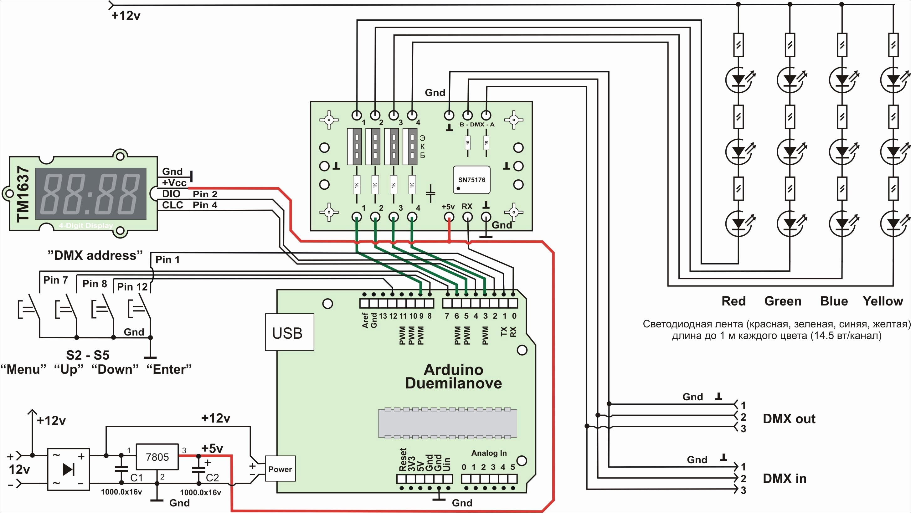
How to wire a smart home top 8 things for smart home wiring. Operating temperatures 0 c 32 f to 40 c 104 f.
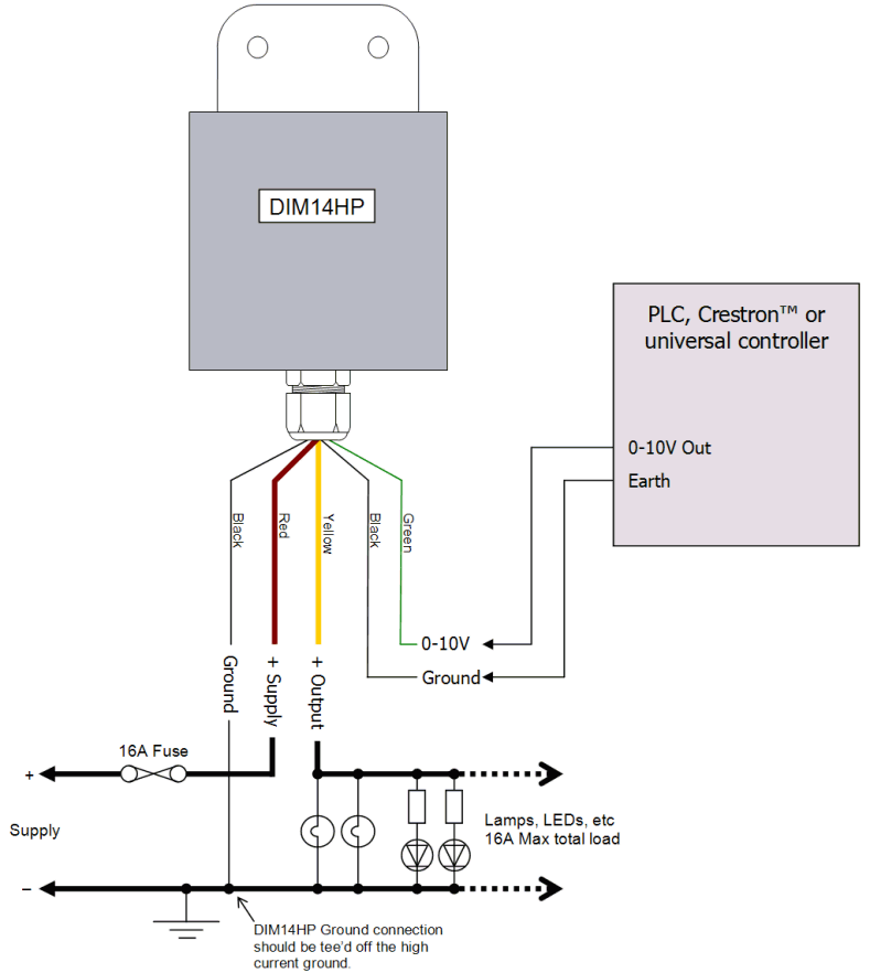
Dim14hp Led Dimmer 0 10 Volt Controlled Waterproof Pwm
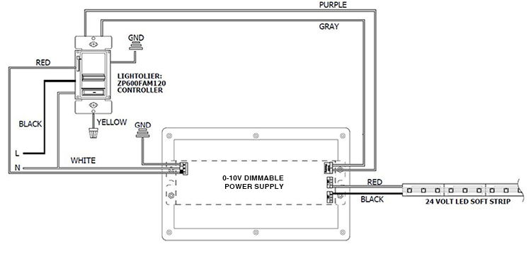
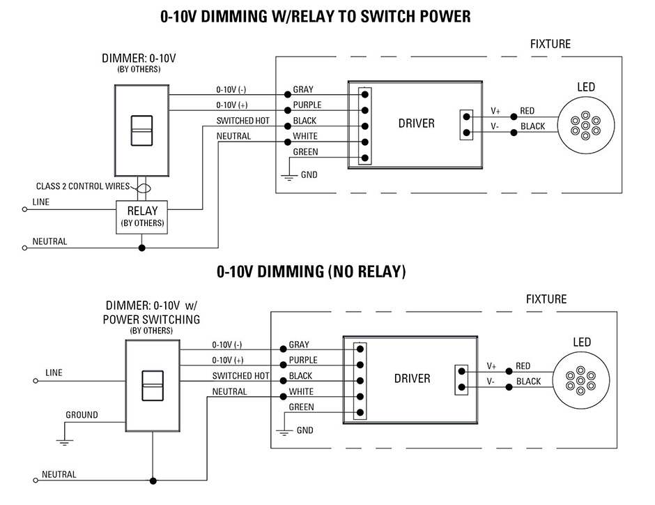
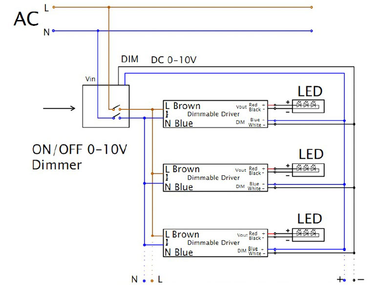
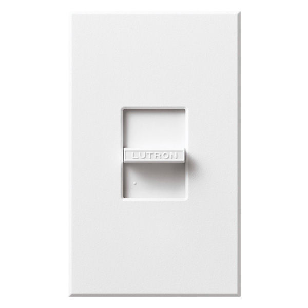
Lutron 0 10 volt dimmer wiring diagram. 0 10v dimming wiring diagram valid wiring diagram for dimmer switch 0 10 volt dimming wiring diagram. Single pole wiring diagram bk black thumbwheel slider top v iolet gray vt gy single pole wiring diagram 3 way wiring diagram wiring diagrams certifications compliances. 0 10 volt dimming basics duration. Wiring diagram not merely offers in depth illustrations of everything you can do but also the methods you should stick to while performing so. Hykolity lighting 5753 views. Volt lighting control devices package contents and parts identification figure a operation the volt low voltage lighting control provides dimming control for volt.
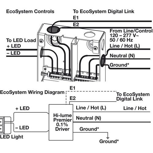
If not the structure will not function as it should be. Black neutral yl line 120v ac 60 hz green or bare white hot load figure 1. Gray dimmer lead to gray connection on ballast. 0 advance mark vii v electronic dimming ballasts lutron eco 10 volt option wire controls according to the appropriate wiring diagram shown inv preset dimmer for use with. A wiring diagram is a simplified standard photographic depiction of an electric circuit. 24 v 100 ma performance power failure memory.
0 10 volt dimming wiring diagram 0 10 volt led dimming wiring diagram 0 10 volt dimming wiring diagram 0 10 volt dimming wiring diagram lutron every electrical structure consists of various different parts. It shows the elements of the circuit as streamlined forms and the power and signal connections between the devices. 0 10 v preset dimmer for use with. Collection of 0 10 volt dimming wiring diagram. Electrostatic discharge tested. Lutron caseta dimmer switch installations.
0 10v dimming wiring diagram 0 10v dimmer switch leviton ip710 lfz or equal for other types of dimming control systems consult controls manufacturer for wiring instructions switched hot black switched hot red typical low voltage dimming wires purple gray typical electrical panel hot black typical 120v or 277v 60 hz neutral white. Wiring diagram 1 insulating label green ground black white red hot black neutral white line 120277vac 60hz dimmer gray yellow to lamps red blue 0 10 vdc ballast yellow red 1 3 7 matching remote additional neutral wire 2 dimmer 2 3 4 red violet white yellowred. Wiring diagrams dimming with onoff control wiring diagram using relay 0 10 v ballastdriver white white red red red. Minimum light level low end shall be adjusted to optimize performance. Decorator 0 10 volt dimmer project name. Each component ought to be placed and connected with different parts in specific way.
0 10 volt lighting control devices package contents and parts identification figure a operation the 0 10 volt low voltage lighting control provides dimming control for 0 10 volt compatible led drivers fluorescent ballast and hid ballast. 0 10 v 30 ma switch. Proceed to step 5. Enviroment for indoor use only.
