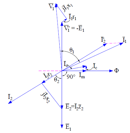
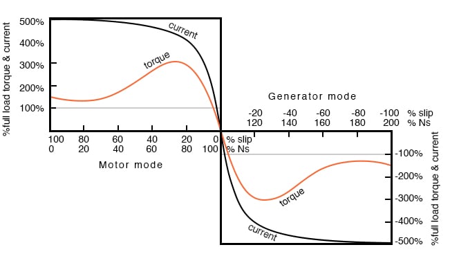
Capacitor start capacitor run motor circuit wiring diagram and torque speed curve. The circle diagram is a graphic representation of the performance of the machine and its drawn in terms of the locus of the input voltage and current.

Circle Diagram Of Induction Motor
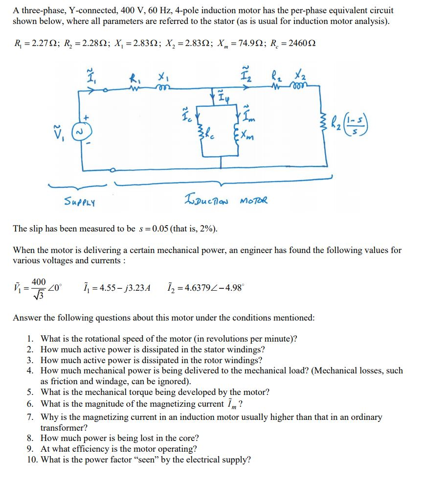
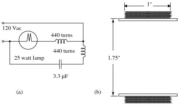
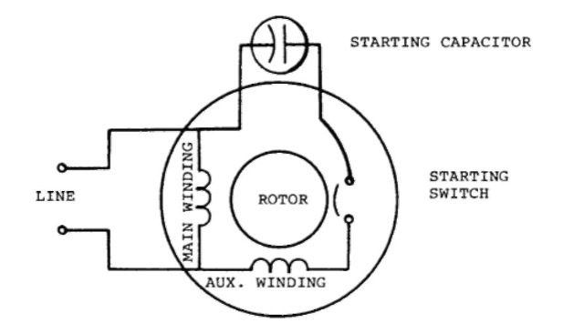
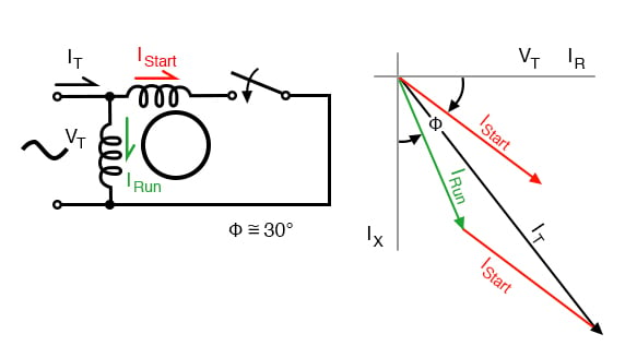
Induction motor diagram. The input power given to an induction motor is in the form of three phase voltage and currents. Capacitor start capacitor run induction motors are single phase induction motors that have a capacitor in the start winding and in the run winding as shown in figure 12 and 13 wiring diagram. An induction motor can therefore be made without electrical connections to the rotor. Induction motor is a generalized transformer. This type of motor is designed to provide strong starting torque and strong running for applications such as large water pumps. The characteristic hump on the top of the motor is where the capacitor is located.
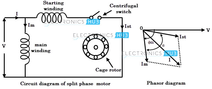
What is an induction motor. Circle diagram of induction motor. Multi phase induction motors by thomas h barton et al lancashire dynamo crypto ltd november 8 1960. To illustrate the simplicity of the ac induction motor. Figure 6 is a photograph of a capacitor start induction motor. A split phase induction motor will not have the hump because it does not have a capacitor.
Difference is that transformer is an alternating flux machine while induction motor is rotating flux machine. An induction motor or asynchronous motor is an ac electric motor in which the electric current in the rotor needed to produce torque is obtained by electromagnetic induction from the magnetic field of the stator winding. Liquid cooling for induction motors by raymond n. The rotor of an induction motor can be a squirrel cage rotor or wound type rotor. An induction motors rotor can be either wound type or squirrel cage type. Will a dimmer switch or transformer control an induction motors speed.
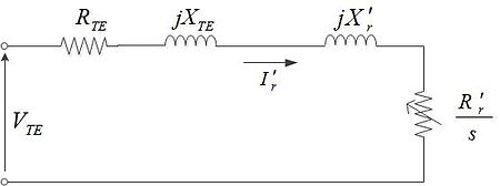
There are two parts lists to choose from depending upon the availability of 120vac or 220vac. Power flow diagram and losses of induction motor power flow diagram of induction motor explains the input given to the motor the losses occurring and the output of the motor. Three ways to run a three phase motor on single phase and the pros and cons of each method 065. To understand the circle diagram of induction motor we should first know what is the circle diagram. And its based on the approximate equivalent circuit. Olson sundstrand corporation january 19 1982.
The power flow diagram of an induction motor is shown below. Choose the one for your location. An induction motor with improved speed control. An induction motor also known as an asynchronous motor is a commonly used ac electric motorin an induction motor the electric current in the rotor needed to produce torque is obtained via electromagnetic induction from the rotating magnetic field of the stator winding. Before deepen in steps of drawing the diagram it. 038 duration.
Rotating flux is only possible when 3 phase voltage or poly phase which is 120 degree apart in time is applied to a three phase winding or poly phase winding 120 degree apart in space then a three phase rotating magnetic flux is. This set of instructions is for the 120vac version. The original ac induction motor patent.
Gallery of Induction Motor Diagram