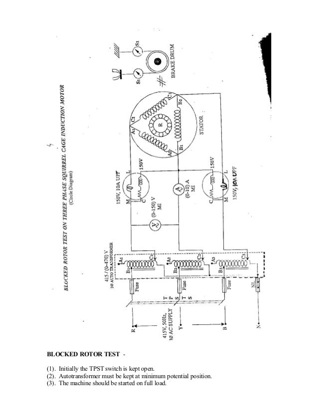
When a 3 phase supply is given to the stator winding it sets up a rotating magnetic field in space. It shows the components of the circuit as simplified shapes and the aptitude and signal links surrounded by the devices.

Squirrel Cage Induction Motors
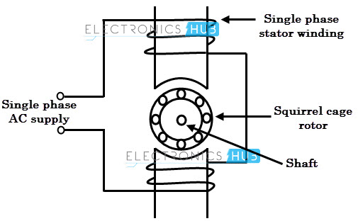
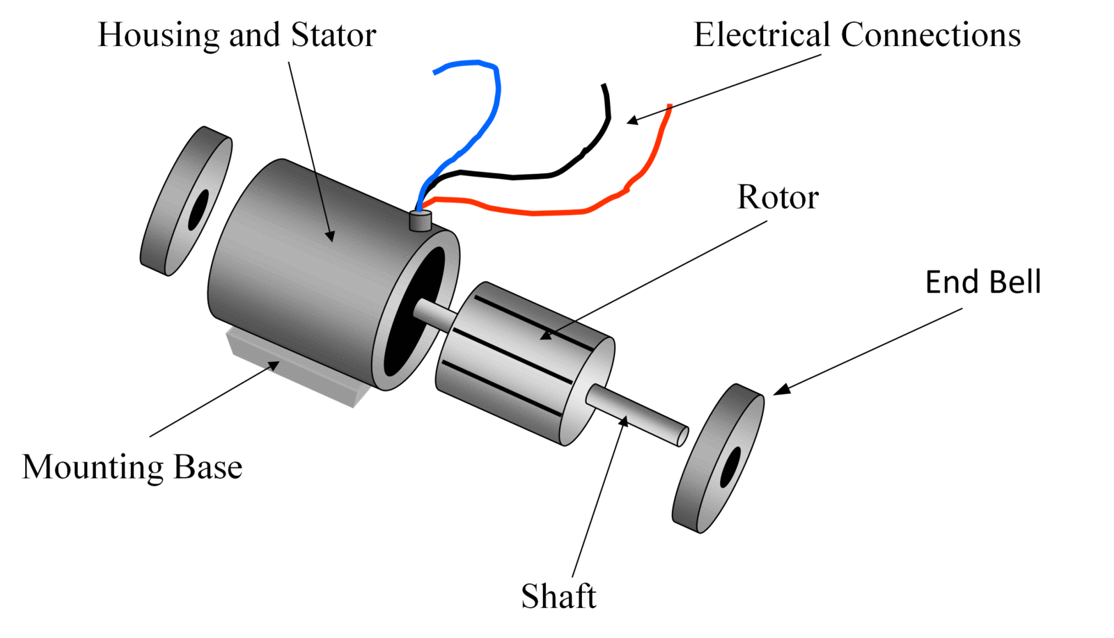
Squirrel cage induction motor diagram. Wiring diagram for squirrel cage motor wiring diagram is a simplified tolerable pictorial representation of an electrical circuit. Motors have main two parts in construction. We saw the construction of the squirrel cage induction motor. Squirrel cage induction motor working principle. When at rest having no induced back emf it can be regarded as a transformer with a short circuited secondary. Repulsion start induction electric motor reversible a repulsion start induction motor is a single phase motor having the same windings as a repulsion motor but at a predetermined speed the rotor winding is short circuited or otherwise connected to give the equivalent of a squirrel cage winding.
Now let us discuss in detail the most common form of induction motor the squirrel cage induction motor. This rotating magnetic field induces the voltage in rotor bars and hence short circuit currents start flowing in the rotor bars. 3 phase squirrel cage induction motor is one of the most popular types of ac electric motor which achieve the electromechanical energy conversion through stator and squirrel cage rotor by electromagnetic induction. This rotating magnetic field has a speed which is known as the synchronous speed. The main difference between slip ring and squirrel cage induction motor is the rotor construction. A squirrel cage rotor is the rotating part of the common squirrel cage induction motor.
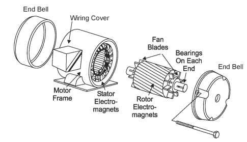
What characterizes an induction motor is the fact that only the stator is connected to the power supply. The alternating current in the stator produces a rotating magnetic field. The rotor winding has current induced in it by the stator field like a transformer except that the current in the rotor is varying. These squirrel cage motors are a step above the shaded pole motors because they can to a little more work with a heavier load attached to the shaft of the rotor. In these motor the rotor is squirrel cage type. It consists of a cylinder of steel laminations with aluminum or copper conductors embedded in its surface.
Normally we use the motors in industrial drives because they are rugged reliable and economical. In operation the non rotating stator winding is connected to an alternating current power source. This rotor is made up from parallel aluminum or copper bars. The rotor of a three phase squirrel cage induction motor consists of a set of non insulated bars that are interconnected by short circuit rings. Split phase motor fig6. The reason for the name squirrel cage is because of the type of rotor used in these motors.
This motor starts as a repulsion motor but. We have seen the classification of ac. Thats why its called squirrel cage induction motor. Motors and discussed in detail the working principle concept behind rotor rotation and many other aspects of induction motor. A squirrel cage induction motor therefore draws a very high starting current as noted in section 121. Split phase motor wiring diagram.
However it reduces. An induction motor can be regarded as a transformer with a small air gap in the magnetic circuit.


