An induction motor or asynchronous motor is an ac electric motor in which the electric current in the rotor needed to produce torque is obtained by electromagnetic induction from the magnetic field of the stator winding. This winding could in fact be used with any ac machine including a synchronous reluctance motor or a wound field synchronous motor or generator.

No 13 Winding Diagram For An Ac Motor Simulation
Ac induction motor diagram. The rotor magnetic field may be produced by permanent magnets reluctance. Thus a capacitor start induction run motor produces a better rotating magnetic field than the split phase motors. An induction motor with improved speed control. The objective of these motor components is to make the rotor rotate which in turn will rotate the motor shaft. To illustrate the simplicity of the ac induction motor. A single phase induction motor is an electric motor that operates on a single waveform of alternating current.
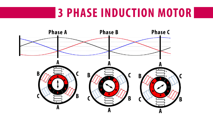
Power flow diagram and losses of induction motor power flow diagram of induction motor explains the input given to the motor the losses occurring and the output of the motor. The rotor then is the rotating part of the ac motor. Multi phase induction motors by thomas h barton et al lancashire dynamo crypto ltd november 8 1960. The power flow diagram of an induction motor is shown below. This set of instructions is for the 120vac version. Three phase induction motor image courtesy.
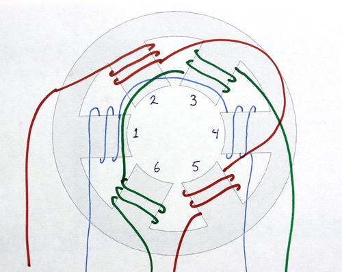
Single phase induction motors are used in residential applications for ac motor appliances in single or multiple dwellings. Here we see a winding diagram for a 3 phase ac induction motor or brushless pm motor ipm having 4 poles and 36 slots. To understand the circle diagram of induction motor we should first know what is the circle diagram. Before deepen in steps of drawing the diagram it. The rotor is located inside the stator and is mounted on the ac motors shaft. The original ac induction motor patent.
Choose the one for your location. And its based on the approximate equivalent circuit. An induction motor can therefore be made without electrical connections to the rotor. The circle diagram is a graphic representation of the performance of the machine and its drawn in terms of the locus of the input voltage and current. Wikipedia single phase induction motors. An ac motor is an electric motor driven by an alternating current ac.
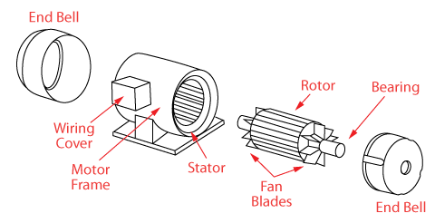
Liquid cooling for induction motors by raymond n. Olson sundstrand corporation january 19 1982. An induction motors rotor can be either wound type or squirrel cage type. The input power given to an induction motor is in the form of three phase voltage and currents. The ac motor commonly consists of two basic parts an outside stator having coils supplied with alternating current to produce a rotating magnetic field and an inside rotor attached to the output shaft producing a second rotating magnetic field. It is important to point out from the phasor diagram that the phase difference between im and is is almost 80 degrees as against 30 degrees in a split phase induction motor.
Circle diagram of induction motor. There are two parts lists to choose from depending upon the availability of 120vac or 220vac. The term rotor is derived from the word rotating. In most respects it is a regular classical example and the objective here is to review some of the features of the diagram and.
Gallery of Ac Induction Motor Diagram

.png)


.png)