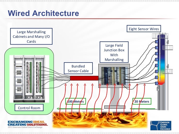
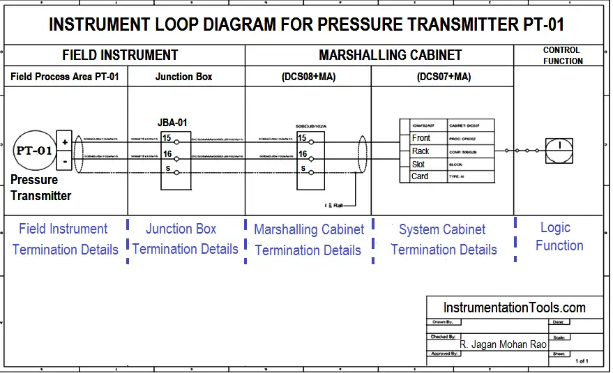
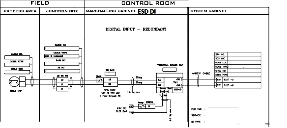
Software download to server and workstations. Internal wiring will be used to connect from marshalling cabinet to system cabinet.
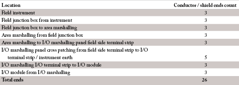
Smarter Marshalling February 2012 Sa Instrumentation
Marshalling panel wiring diagram. Wiring between marshalling and system cabinets. Installation and wiring of operator workstations. Electronic marshalling provides separation between ie hardware installation schedules and control strategy development. Power is supplied by connecting a step down transformer to the control electronics by connecting to phases l2 and l3. Figure 1 a motor controller schematic. Electronic marshalling provides io type connectivity in a single channel component called a characterization modules charm.
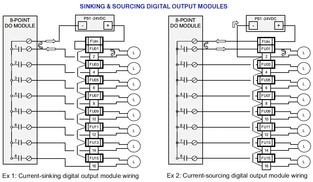
Cnc plc training by krishna automation 153612 views 2610. Plc training siemens wiring inputoutput sourcesink practical in hindi by gopal sir p47 duration. The klik marshalling box can be separated into two independently switched. For example lets say we have a 24 pair incoming field cable that carry 20. Cross wiring is always necessary since the incoming field signal and the channel quantity of the io card is always different. Panel wiring power and signal in accordance with wiring diagram.
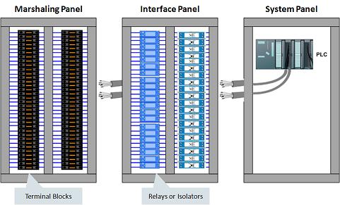
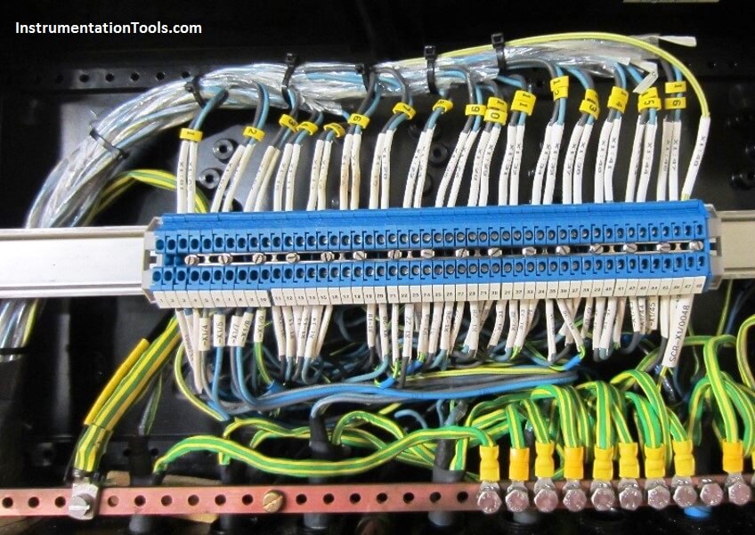
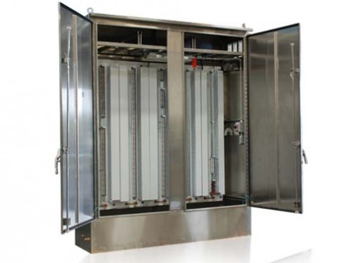
Marshalling helps reduce overall system costs by eliminating internal cabinet cross wiring reducing overall footprint simplifying io channel assignments and reducing factory authorized testing activities. Hardware configuration and config file creation. One of the important interface function of the marshalling cabinet is the cross wiring function. The lower voltage is then used to supply power to the left and right rails of the ladder below. Charms allows field wiring of any signal type to be terminated anywherethis means no marshalling cabinet or cross wiring fewer wires much less work and fewer contact points for potential failures. Marshalling cabinet main purpose is to provide main cables termination and then re distribute the field devices to respective analog inputoutput card using internal wiring.
Service centre 25 klik 4 pin wiring diagrams local lightingnov 06 wiring diagram of klik ax. Wiring diagrams of plc and dcs systems di do ai ao x liquid level control using flow loop control systems since liquid level can only change in a vessel if there is an imbalance of inlet and outlet flow rates would this system be practical to achieve stea. Marshalling cabinet or marshalling panel. Modification of loop with 250ω resistor to covert 4 20ma to 1 5v. The contacts m will be controlled by the coil mthe output of the motor starter goes to a three phase ac motor.

