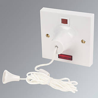
If the feed is at the pull cord switch loop a live in to the isolator off the switch loop a switched live in to the isolator off the switch and a neutral off your light fitting to the isolator. Bathroom exhaust fan wiring diagram for switch to light fokus wiring a bathroom extractor fan with an isolator switch selv bathroom fan wiring diagram base website 1a77d04 bathroom extractor fan wiring diagram uk library how to wire an electric shower uk you.

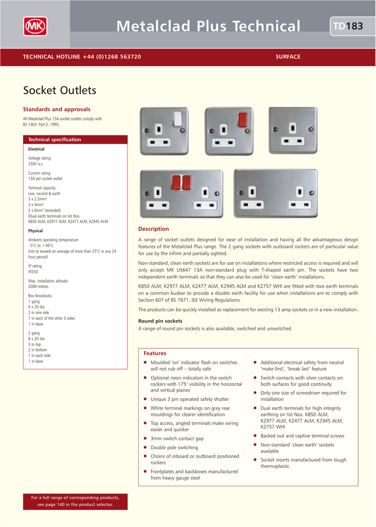
Mk Metal Clad Technical
Mk fan isolator switch wiring diagram. Electrical product mk electric home gb products wiring devices mk dimensions three pole fan isolator. The switch has provision for a locking device k4858 if bought separately to ensure that it cannot be accidentally switched back on. The lugs in the. Remove the existing socket or switch from the wall if replacing. When the switch is in the off position a hole at each end of the switch actuator is exposed fig. Remove any plaster debris and dust from the inside of the wall box.
1 gang 10a 3 pole fan isolator switch. Mk fan isolator switch 3 pole 10a. Mhfp010bss mhfp010sst mhfp010sbr mhfp010brz mhfp010whi mhfp010lts mhfp010dks mhfp010chm mhfp010mbk. The supply will be coming from a junction box. The terminal layout may vary from one socket or switch to another therefore carefully check the location of the terminal connections before wiring. Always use the correct type of cable that is rated appropriately.
Mk fan isolator switch 3 pole with padlock is rated out of 5 by 4. As long as you have a live switched live and neutral going to your isolator first the rest is simple to feed to the fan all as above diagram. Sep 04 fitting a 4pole 32a rotary isolation switch to act as an isolator in a twin and earth wiring single phase 16a circuit leading to an invertor the supplied switch from screwfix doesnt have a. It enables the fan to be isolated and subsequently disconnected for repair or maintenance.


