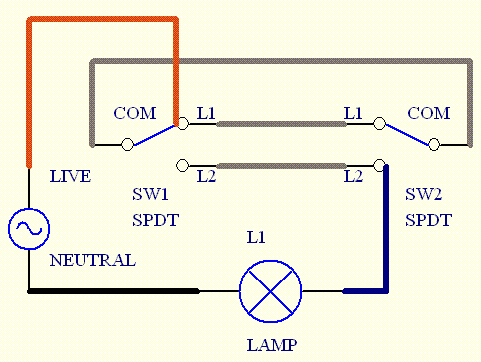
Terminal 1 is connected to a fan. This is the new method to make a 2 way switching connection as it is slightly different from the two wire control method.

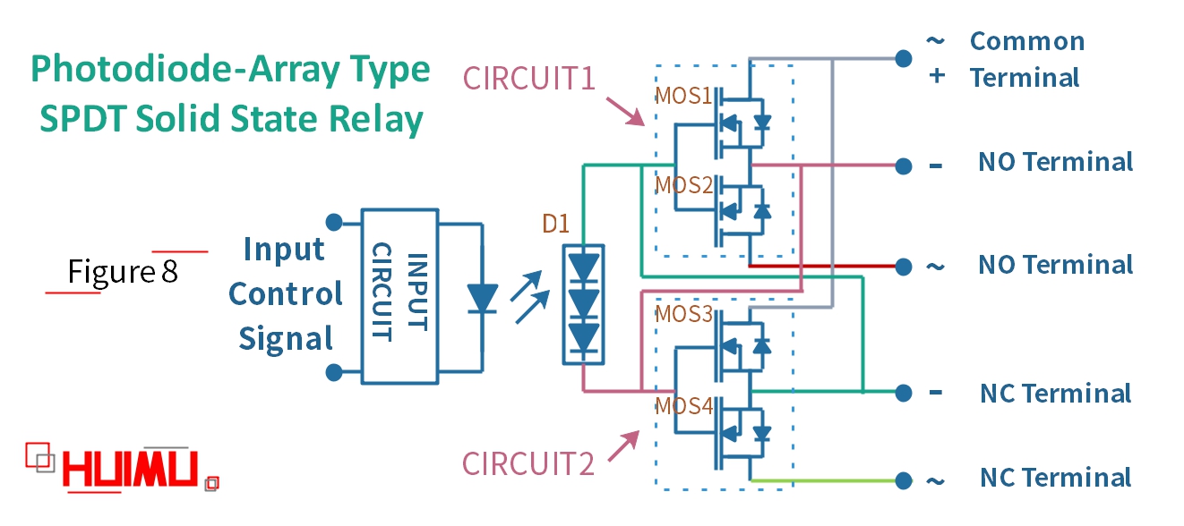
Edn Mosfet Pair Makes Simple Spdt Switch
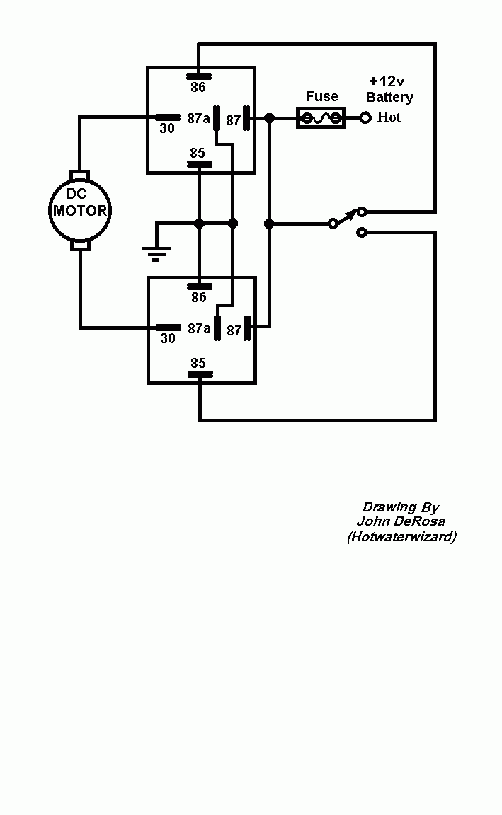
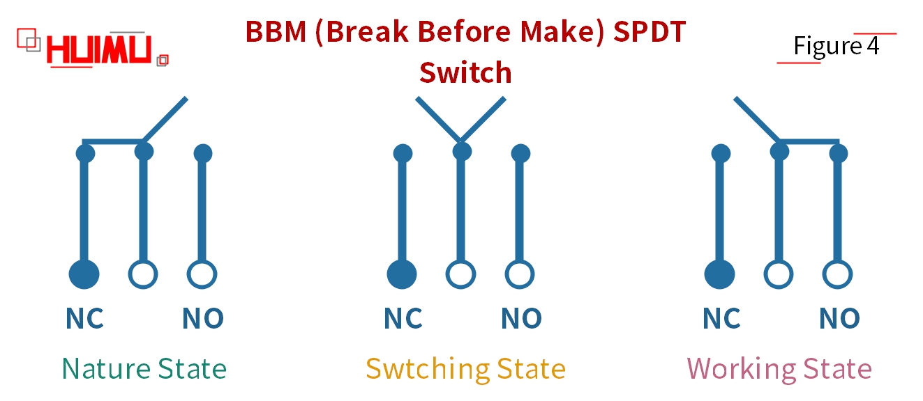
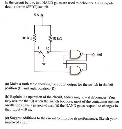
Spdt switch circuit diagram. That turns a single circuit on or off. A second spdt switch is used to select the adjustable voltage regulators output value by adjusting a voltage divider. On this breadboard power supply an spdt switch is used to turn the circuit on and off. In tunnel wring circuit diagram we have used spdt two way switches to control the lighting points in tunnels and corridors. Variety of spdt toggle switch wiring diagram. Pole refers to the number of circuits controlled by the switch.
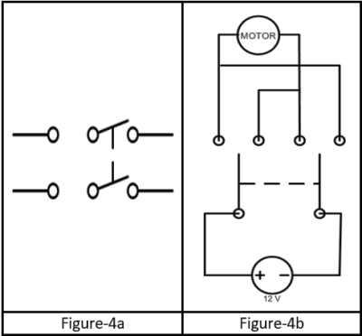
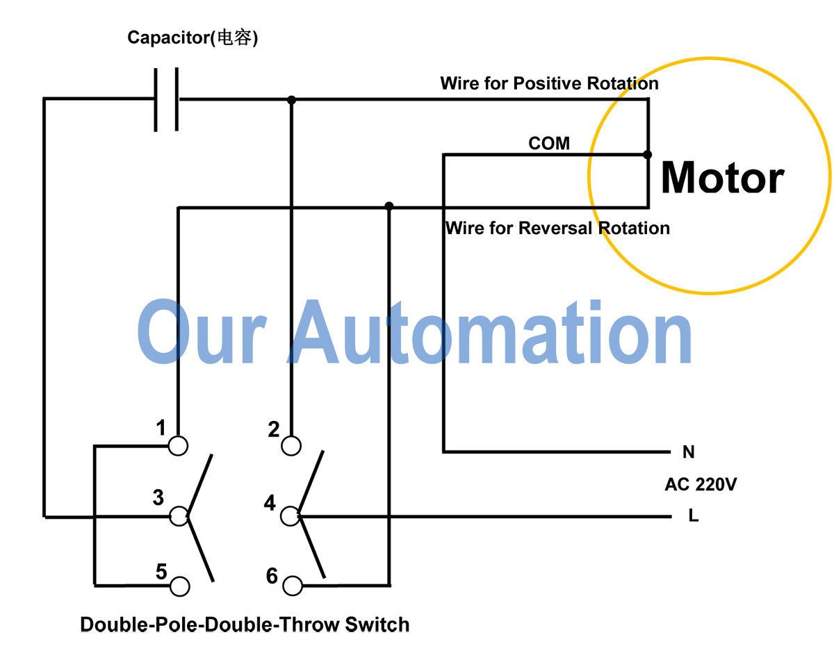
This type of switch is sometimes called an ab switch because it lets you choose between two circuits called a and b. One for the input and one for the output. When the dpdt switch is switched one way flipped upward in the diagram the lamp and buzzer are both on while the led and speaker are off. How to connect 2 way switch wiring using three wire control. Tunnel wiring circuit diagram working and operation. Below is an example of a circuit which utilizes a double pole double throw switch.
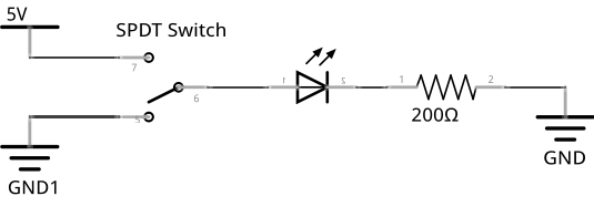
A circuit diagram with an led resistor and a switch. An example circuit of a spdt toggle switch is shown below. A wiring diagram is a streamlined standard photographic depiction of an electrical circuit. It shows the elements of the circuit as simplified forms and also the power and also signal links between the tools. It shows the elements of the circuit as simplified shapes and also the power and also signal connections between the tools. Variety of spdt rocker switch wiring diagram.
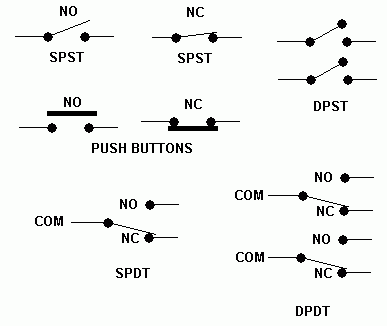
Sp and dp refer to single pole and double pole st and dt refer to single throw and double throw. You can see above how a double pole double throw switch can allow a circuit to be in 1 of 2 modes. An spst switch has two terminals. When we flip the switch to the left terminal 1 the dc fan runs while the dc motor does not. Sp switches control only one electrical circuit. An spdt switch routes one input circuit to one of two output circuits.
When the switch is closed current flows and the led can illuminate. Terminal 2 represents the toggle switch which we can flip between terminals 1 and 3. In this circuit we connect our 9 volt dc power source to terminal 2. Dp switches control two independent circuits and act like two identical switches that are mechanically linked. Where 0 represents the off condition and 1 represents the on condition. What do spst spdt dpst and dpdt mean.
A wiring diagram is a simplified traditional pictorial depiction of an electrical circuit. This method is commonly used now days as it is efficient than the two wire control system. The tunnel circuit control the lamps in four ways as follow. Spdt single pole double throw. In corridor wiring circuit a lighting point is controlled from two different locations using 2 way switches. Hallway and corridor wiring circuit diagram using two way switches.
Tunnel wiring circuit is used in open ended corridors and short tunnels like structures. Basically this circuit is same like staircase wiring circuit using two way spdt switches used to control the lighting circuit in a hallway and corridors.
