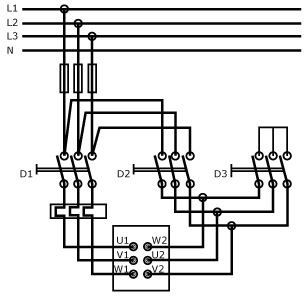
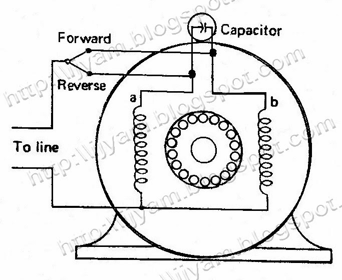
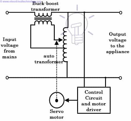
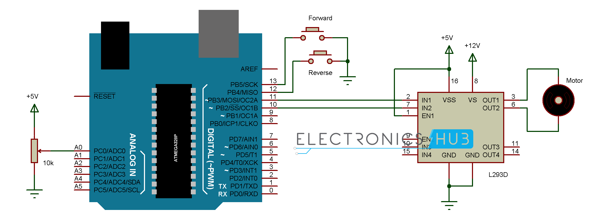
In this way you can always check that you have been through all steps. file 00836 question 4 interpret this ac motor control circuit diagram explaining the meaning of each symbol.

An6651 Datasheet Datasheets Manu Page 1 Motor Control
Motor control circuit diagram pdf. Many smaller motors use the same size. O the project looks like pcsmotordemo1. Imagine trying to wire a pushbutton station for a 100a motor using 3 awg conductors. Tutorial motor control o shows you how to make a small control circuit where all components are found in the component database. Eaton wiring manual 0611 8 1 88 all about motors page motor protection 8 3 notes on engineering 8 15 circuit documents 8 19 power supply 8 21 control circuit supply 8 24 contactor markings 8 25 direct on line start of three phase motors 8 26 control circuit devices for direct on line start 8 34 star delta switching of three phase motors 8 35. The finished project contains electrical diagrams panel mechanical layout and various lists.
Gamma ec d 5051 diags. What happens when someone actuates the. A line diagram may be used to illustrate a manual control circuit of a pushbutton. Fundamentals of motor control created date. L1 l2 run m1 to 3 phase motor power source m1 also explain the operation of this motor control circuit. In this particular case i show a low voltage control circuit and a 3 phase higher voltage motor.
Wiring diagram calls for something different. Motor 3ct to 120 v separate control ot is a switch that opens when an overtemperature condition exists type mfo and mgo only t1 t3 motor 3 2 l2 t2. It is your job to improvise a solution. A very common form of latch circuit is the simple start stop relay circuit used for motor controls whereby a pair of momentary contact pushbutton switches control the operation of an electric motor. Motor control wiring diagram pdf wiring diagram is a simplified usual pictorial representation of an electrical circuitit shows the components of the circuit as simplified shapes and the facility and signal associates with the devices. Motor control circuits motor control circuits are an effective way to reduce cost by using smaller wire and reduced amperage devices to control a motor.
These diagrams apply to intelligent control motorsthat are fitted to the following products pgs ocdeec. Wiring diagram book a1 15 b1 b2 16 18 b3 a2 b1 b3 15 supply voltage 16 18 l m h 2 levels b2 l1 f u 1 460 v f u 2 l2 l3 gnd h1 h3 h2 h4 f u 3 x1a f u 4 f u 5 x2a r power on optional x1 x2115 v. Rockis 2001 manual control circuits manual control circuit any circuit that requires a person to initiate an action for the circuit to operate. Ic1 2 ocdeecvglgl gamma ec d 5253 diags. 4 electric motor controls g. These diagrams are current at the time of publication check the wiring diagram supplied with the motor.


