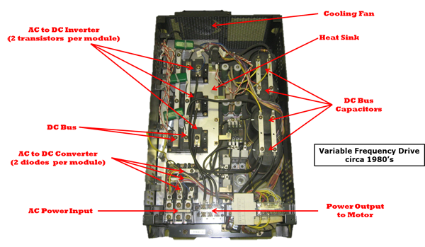
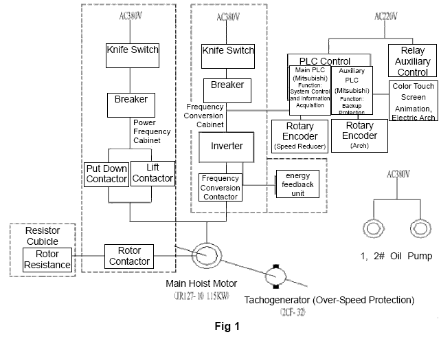
O the project looks like pcsmotordemo1. 1 opened variable frequency drive for troubleshooting following fig.

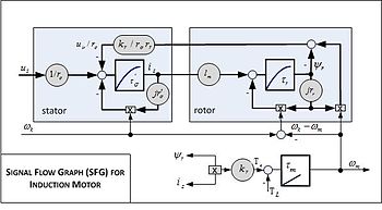
Vector Control Motor Wikipedia
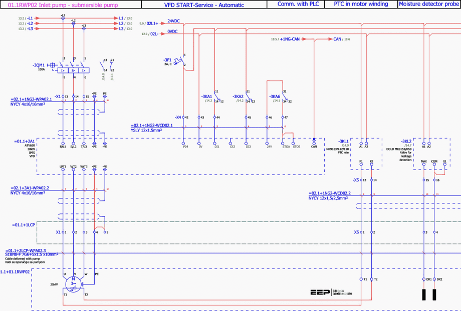
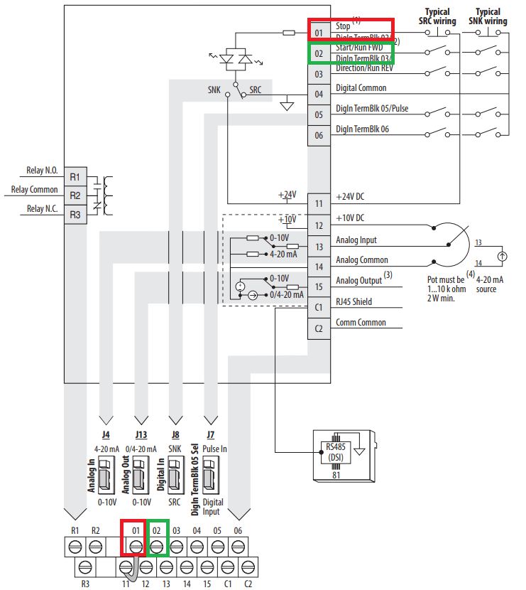
Vfd motor control circuit diagram pdf. The frequency determines the motor rpm and by controlling the ac frequency the motor rpm can be controlled. I am here with giving you a vfd start stop wiring diagram for running a vfd through panel board push button and keypad of the vfd it is called hmi. Vfd start stop wiring diagram. Tutorial motor control o shows you how to make a small control circuit where all components are found in the component database. 4 pole motor at 60 hertz 1800 rpm 4 pole motor at 50 hertz 1500 rpm 4 pole motor at 40 hertz 1200 rpm. The finished project contains electrical diagrams panel mechanical layout and various lists.
Speed the motor runs at when fully loaded and supplied rated nameplate voltage. Also the motor can be slowly brought up to speed eliminating huge start up current spikes. For simplistic purposes this motor drive will be split into two main components. In this way you can always check that you have been through all steps. Vfd principles of operation motor speed can be varied by changing the frequency of poles or both. Vfd is a short form of variable frequency drive or variable voltage variable frequency drivethe vfds are working based on changing the input frequency and input voltage of the motor we can change the speed of the.
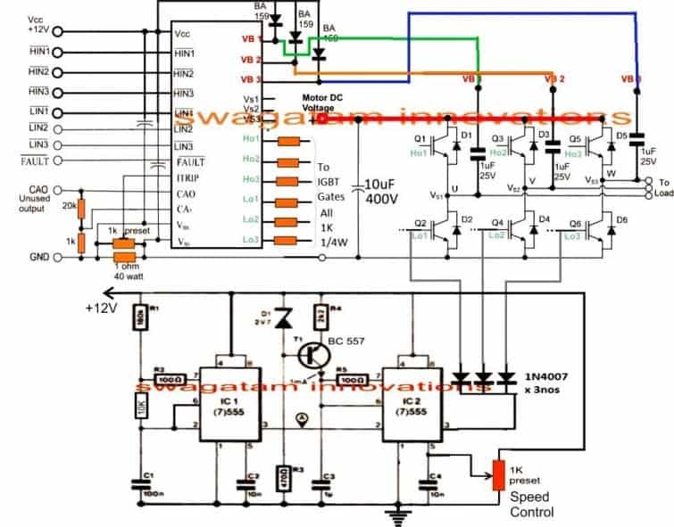
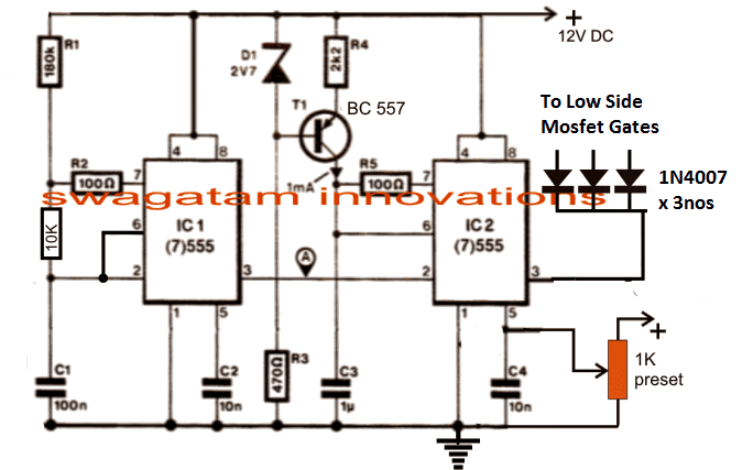
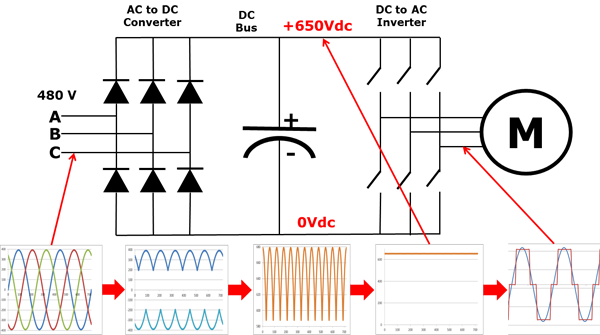
2 diagram shows an electronic diagram of a gozuk vfd. Vfd is the short form of a variable frequency drive or adjustable frequency drive. Different types of vfds are available in the electronics and electrical market ranging from small motor related applications to the high power induction motors. That the motor only sees the necessary amount of input power to achieve desirable output power. The ac dc and the dc ac converters which will contain the control circuit. The third block of the vfd is called the inverter section because this is where the dc voltage is turned back into three phase ac voltage.
