It acts as a switch and a signal amplifier. In this switching circuit where n channel is used and the gate source terminals are supplied by the positive polarity of the voltage.

Mosfets And Cmos Inverter Elec2210 V1 0 Documentation
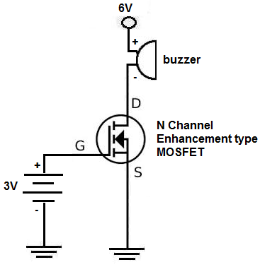
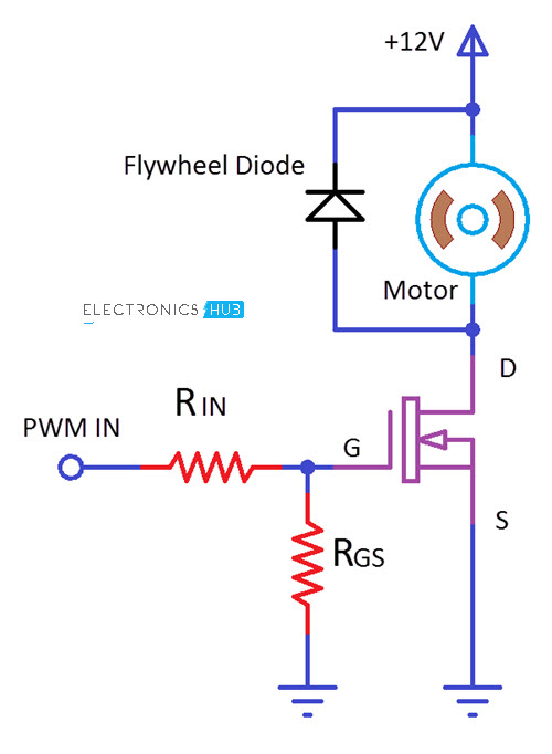
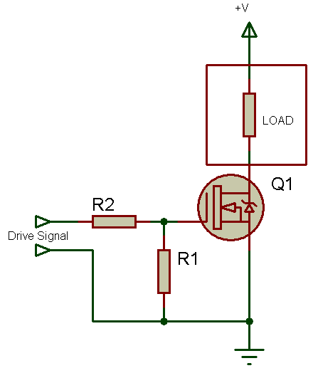
N channel mosfet switch circuit diagram. Assume the device is initially off. The schematic for the n channel mosfet circuit we will build is shown below. The positive gate voltage is applied to the base of the transistor and the lamp is on v gs v or at zero voltage level the device turns off v gs 0. N channel mosfet circuit schematic. V gs is made appropriately positive technically speaking v gs v th. In this circuit arrangement an enhanced mode and n channel mosfet is being used to switch a sample lamp on and off.
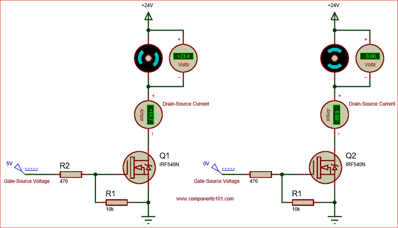
When mosfet is in cut off triode region it can work as switch. For an 2n7000 mosfet 3v at the gate is more than sufficient to switch the mosfet on so that it conducts across from. So this is the setup for pretty much any n channel mosfet circuit. The voltage across gate and source ie. In order to operate a mosfet as a switch it must be operated in cut off and linear or triode region. Mosfet works in three regions cut off region triode region and saturation region.
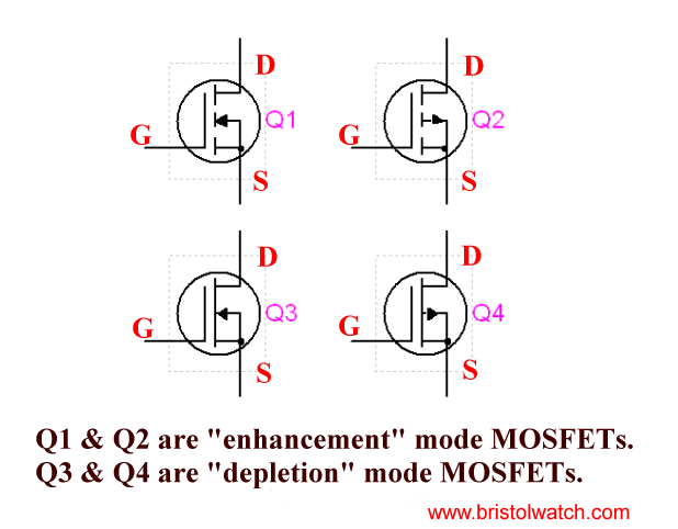
The circuit symbols for each are shown in fig. This is a simple circuit where a n channel enhancement mode mosfet will turn on or off a light. Unlike a junction transistor which controls a large current with a smaller one a mosfet controls current with a voltage. Mosfet switching circuits consists of two main part mosfet works as per transistor and the onoff control block. N channel mosfet switch circuit. Mosfet passes the voltage supply to a specific load when the transistor is on.
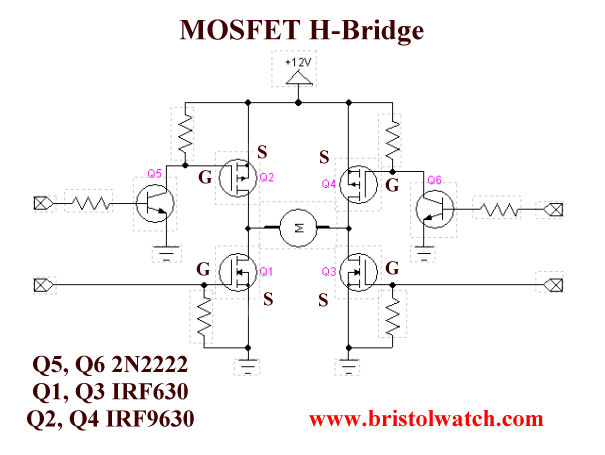
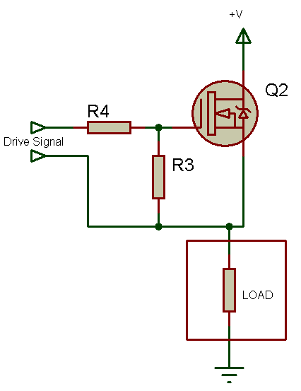
A mosfet is a transistor that uses the effects of an electric field to control the flow of current. Positive voltage is fed into the gate terminal. In this circuit arrangement an enhancement mode n channel mosfet is being used to switch a simple lamp on and off could also be an led. Similarly the drain is where the charge carriers leave the channel. The high side mosfet switch. If the mosfet is a p channel or pmos fet then the source and drain are p regions and the body is a n region.
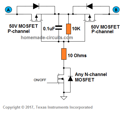
To make high side switching possible there are a number of methods that can be used. This positive polarity makes the device that is connected to the transistor makes it turn on. In most of the cases n channel mosfets are preferred. The gate input voltage v gs is taken to an appropriate positive voltage level to turn the device and therefore the lamp load either on v gs ve or at a zero voltage level that turns. The arrow marks in the symbol indicates the direction of flow of charge carriers. Mosfets come in two polarities p channel and n.
The simplest of these is to replace the n channel mosfet with a p channel type. The source is so named because it is the source of the charge carriers electrons for n channel holes for p channel that flow through the channel.
Gallery of N Channel Mosfet Switch Circuit Diagram