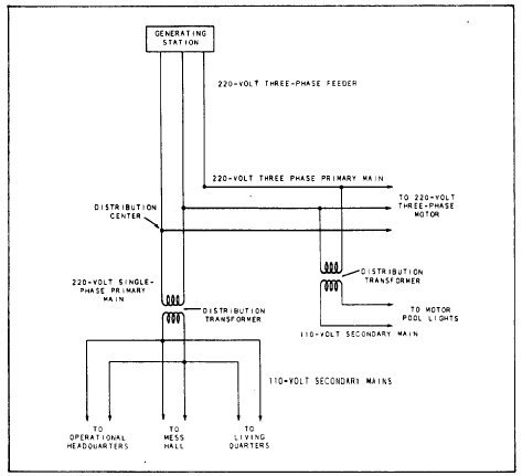
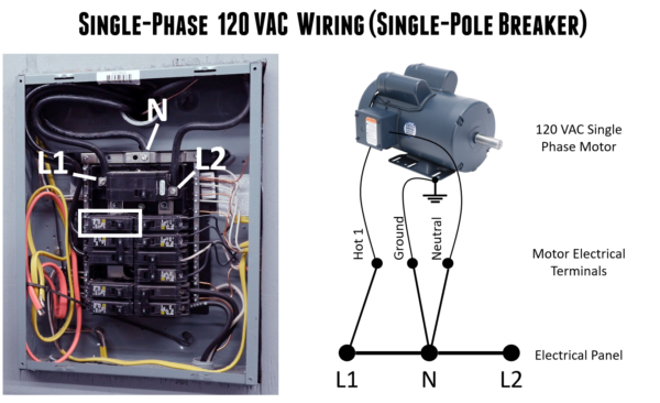
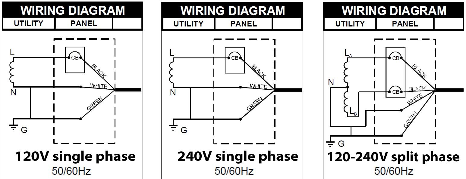
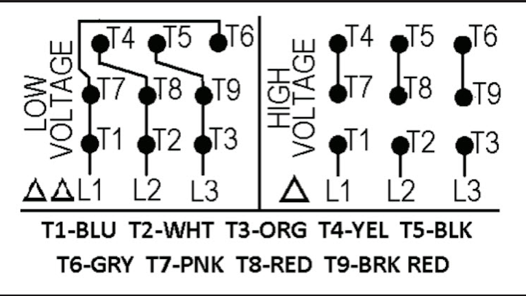
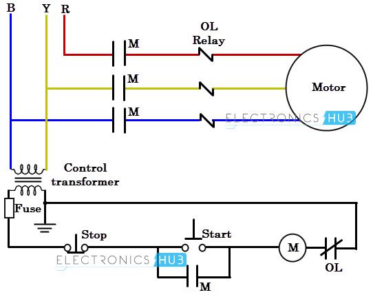
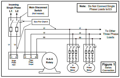
It reveals the components of the circuit as simplified shapes as well as the power and also signal connections in between the tools. Both of these wires supply the current to the appliance and return the current to the service panel.

Power Distribution Single Phase And Three Phase
Three phase to single phase wiring diagram. 3 inside three phase converter wiring diagram rotary wiring a novice s overview of circuit diagrams a very first appearance at a circuit diagram may be confusing yet if you could check out a subway map you could check out schematics. Single phase three phase wiring diagrams 1 phase 3 phase wring the star delta y δ 3 phase motor starting method by automatic star delta starter with. Variety of 240v motor wiring diagram single phase. Single phase wiring installation is the most common wiring in residential buildings. From the electric pole to wire comes. Home about us news wiring a single phase motor through a 3 phase contactor.
This is sometimes called phase to phase wiring and is most commonly used for a heater and air conditioners. The 1 phase when connected to an electric motor is not able to develop a revolving magnetic field. A 240 volt single phase wiring uses two hot wires. This type of motor is designed to provide strong starting torque and strong running for applications such as large water pumps. Drawbacks of the single phase system can be overcome in a three phase supply system. Single phase power is typically reserved for lower power requirements however in some cases powering a small motor with single phase input power is practical.
1 phase motors require some additional equipment to start. Single phase power is commonly called. The concept of single phase electrical meter or single phase energy meter. The 1 phase cannot be applied for heavy loads. After watching this video you can make the connection of electricity meter at home. Capacitor start capacitor run induction motors are single phase induction motors that have a capacitor in the start winding and in the run winding as shown in figure 12 and 13 wiring diagram.
Drawbacks of the single phase system. In single phase supply 230v in uk eu and 120v in us canada there are 2 one is line live and the other one is neutral incoming cables from the utility poles to energy meter and then directly connected to the main distribution board consumer unit. A wiring diagram is a streamlined conventional pictorial depiction of an electric circuit. The difference between three phase and single phase is primarily in the voltage that is received through each type of wire. Posted january 18 2018 by springercontrols. The difference between single phase three phase electrical wiring.
There is no such thing as two phase power which is a surprise to some people. Wiring a single phase motor through a 3 phase contactor.

