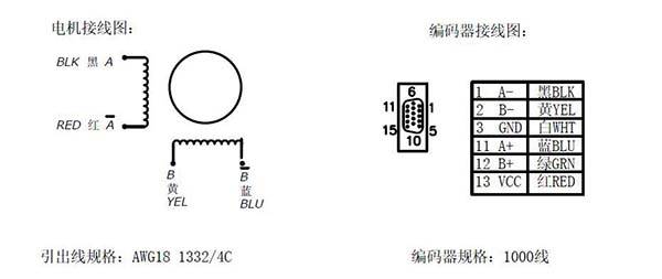
Red green yellow and blue. Closed loop find more 3 items of products in closed loop closed loop stepper driver 082a 2080vac or 30100vdc for nema 34 motor closed loop stepper driver 082a 2480vdc for nema 34 stepper motor closed loop stepper driver 0 70a 24 48vdc for nema.

Us 99 19 9 Off High Torque Toauto 1 8 Degree 5 6a 12nm 86mm Nema 34 Stepper Motor With Driver Kit Hb 860h 86bygh250d For Cnc Engraving
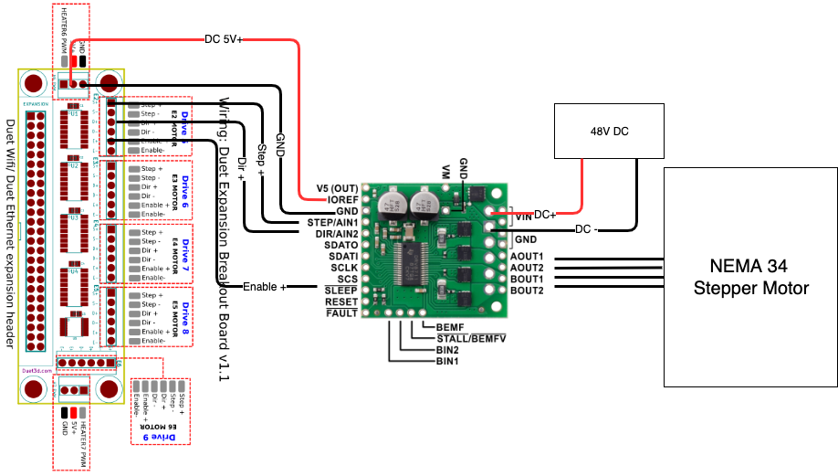
Nema 34 stepper motor wiring diagram. Hard coeur garage 146101 views. These instructions are intended for those with prior electronics. Dm860a drivers nema34 stepper motors db25 1205 breakout board bob. Nema 34 wiring instructions. Longs 3 axis cnc kit part 1. Since coils a and b on the diagram above are not connected the resistance between leads a1 and b1 or between a1 and b2 will be infinite.
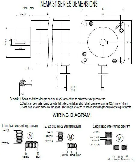
Wiring diagram for nema 34 stepper motor is given below. Nema 34 series 3 phase stepper motors datasheet leadshine america inc. These wires are connected to two different coils. Plans info instructions configuration archived instructions nema 34 wiring instructions. If your stepper motor has 4 wires it is a bipolar stepper motor. Electrical specification manufacturer part number.
I was to get it to go but would have helped to have a wiring diagram and manual for breakout and stepper motor driver and the color coding for the wires on the stepper motor. Nema 34 stepper motor high speed demo 4000 rpm duration. This bipolar nema 34 stepper motor with step angle 18deg and size 858x858x68mm. Here is a video of the basic wiring for the longs 3 axis 1232ozin stepper motor conversion kit. 1 3 nema 34 series 3 phase stepping motor datasheet. Youll need an ac power cable a dc power supply some 18 awg or larger wire to connect the power supply a motor a motor cable a parallel port cable and of course a g540.
Note this guide shows a 73a power supply for a 3 axis system but the process is the same for the 4 axis system youll just be using the larger 125a supply. Bipolar stepper motors have two windings which are not connected to each other wired internally like this. 4pcs nema 23 stepper motor steel mounting bracket with mounting screws 49 out of 5 stars 36. Red and green connected to one coil while yellow and blue are connected to other. It has 4 wires each phase draws 400a with holding torque 34nm 481576ozin. As shown in wiring diagram there are four wires of different colours ie.
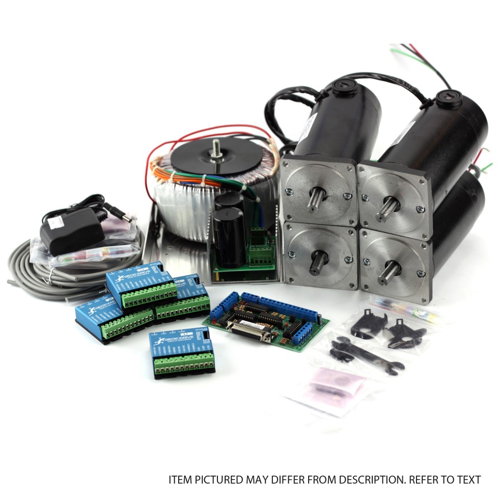
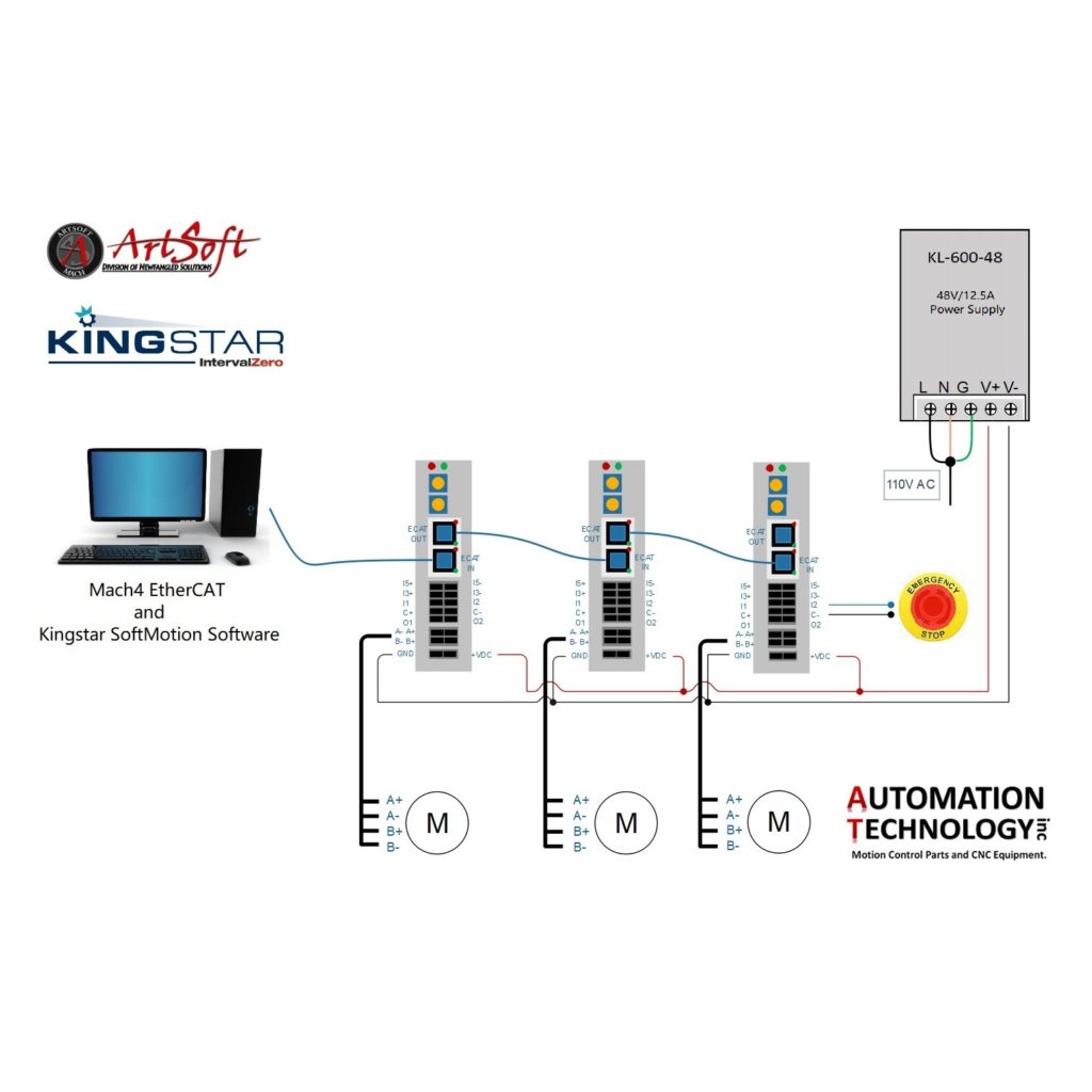
25 mauchly suite 318 irvine ca 92618 usa tel. The following documentation illustrates how our turn key plug and play nema 34 cnc control system is configured and wired.


