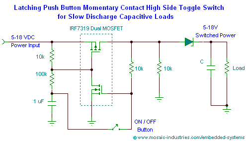
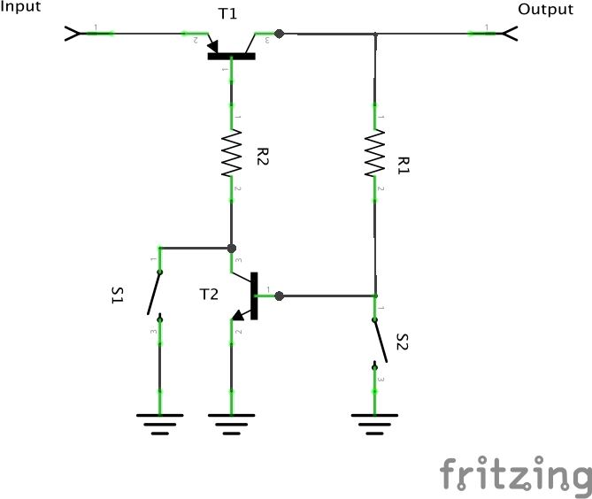
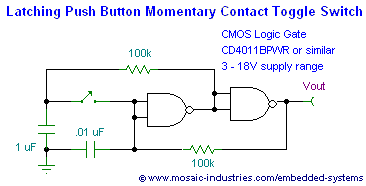
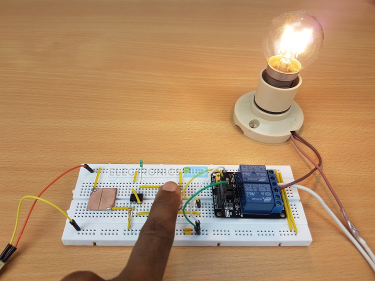
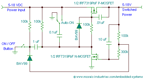
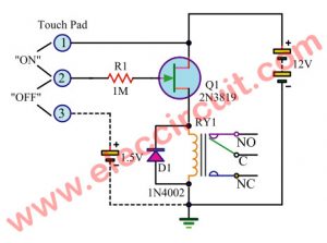
Touch switch circuit project. A schematic diagram of a touch switch circuit is shown below.
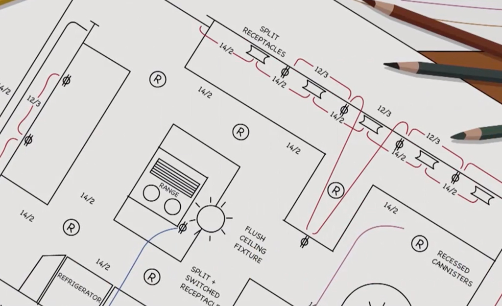
How To Install A Circuit Breaker The Home Depot
One touch on off switch circuit diagram. Multiple light wiring diagram. Few electronic elements only available in the market with high sensitivity and high reliability. In this circuit a n channel mosfet irfz44n is used as switching element. The hot and neutral terminals on each fixture are spliced with a pigtail to the circuit wires which then continue on to the next light. Today we let to play a simple digital circuit. This touch switch circuit is composed from an current amplifier and a decimal counter circuit.
In this video i will show you how to make touch on touch off switch with relayon off switchlatching relay the correct schematic diagram of this circuit. In this touch switch circuit two ics are used one is 555 timer ic and second is d flip flop 7474 ic. On off any appliance using single touch plate. The output terminal pin3 connected with led here you can connect relay switch to control any device. It is set to form as flip flops. When once touch touch the touch plate the light is on again if you touch the light is switched off.
You can say that on off using one touch plate or one touch point this circuittouch. It is a one shot touch switch control. This diagram illustrates wiring for one switch to control 2 or more lights. This circuit will turn on off an electronic relay using the same touch sensor. The at42qt1012 is an one channel toggle mode touch sensor ic with power management functions. 1 x 33 mω resistor 14 watt 1 x 1 mω resistor 14 watt 1 x bulb with holder regular or cfl 1 x 5v relay module if relay module is not available then you need the following components 1 x 5v.
The logic hi at an output when your finger touchpad and is a time delay for 3 seconds. I use ic 4011 digital cmos is base of a circuit. Very simple touch switch circuit for touch on and touch off for appliance. 1 x 555 timer ic. This is simple touch on off switch circuit diagram using mosfet. A very simple touch switch circuit diagram can be constructed using this circuit schematic.
And a relay is connected to give the supply to the load such as ligh bulb fan etc. Placing ground supply plate near to trigger pin makes on switch and placing positive supply plate near to threshold pin makes off switch. The touch terminal is used to trigger this circuit. Share on tumblr electronic circuits with touch sensing is more interactive to the user than traditional electronic circuits. The circuit diagram for the touch on and off switch circuit is shown in the below image. Here the ic at42qt1012 from atmel is in the top preferred list to us.
As timer this circuit uses 555 timer which is connected to one shot multivibrator. This circuit consist of timer one shoot multivibrator and touch terminal. The source is at sw1 and 2 wire cable runs from there to the fixtures. Make touch metal piece for on off control and then place with trigger pin2 input and threshold pin6. The counter circuit is a cdb490 type and is capable to show at pin 12 states.

