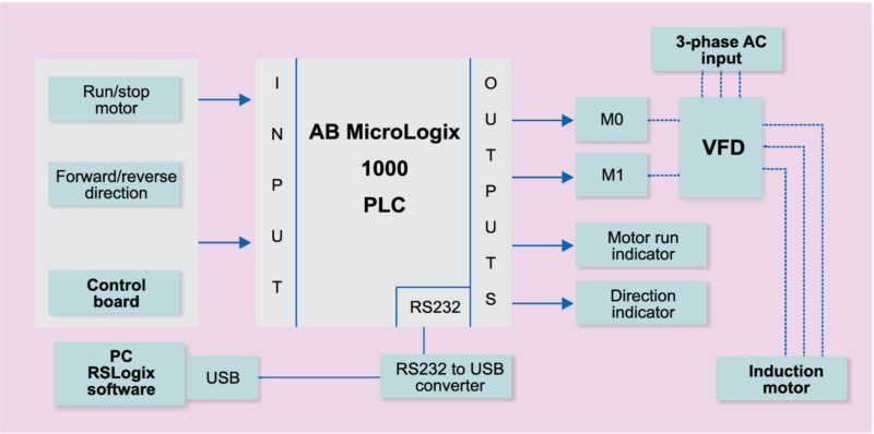
Schematic diagrams schematic diagrams show components in their electrical sequence without regard for physical location. Figure 5 below shows a schematic diagram for a plc based motor control system similar to the previous motor control example.
Control Engineering Control Engineering Hot Topics July 2019
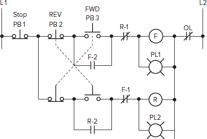
Plc control circuit diagram. Siemens the following line diagram illustrates how a normally open and a normally closed pushbutton might be connected to control a three phase ac motor. Because of diagnostic capabilities in category 2 4 it is not required to use well tried components in those categories. A wiring diagram is a simplified conventional photographic representation of an electric circuit. Since plc program elements are typically designed by single letters i will call the internal control relay c1 rather than cr1 as would be customary in a relay control circuit. As an introduction to ladder diagrams consider the simple wiring diagram for an electrical circuit in figure 1athe diagram shows the circuit for switching on or off an electric motor. On the other hand a plc for example is not a well tried component.
This figure shows the e stop wired to cutoff power to all of the devices in the circuit including the plc. If we wanted to keep the motor running even after the operator takes his or her hand off the control switches we could change the circuit in a couple of different ways. Plcs can range from small modular devices with tens of inputs and outputs. Just like on the diagram we start with the stop push button. Schematic diagrams are used to troubleshoot and install control circuits. It shows the elements of the circuit as streamlined shapes as well as the power as well as signal connections in between the tools.
We could replace the push button switches with. Im using the siemens tia portal as the plc programming software. The interlock contacts installed in the previous sections motor control circuit work fine but the motor will run only as long as each push button switch is held down. These look like a normally closed nc contact. Assortment of plc panel wiring diagram pdf. But it does tend to become more complex.
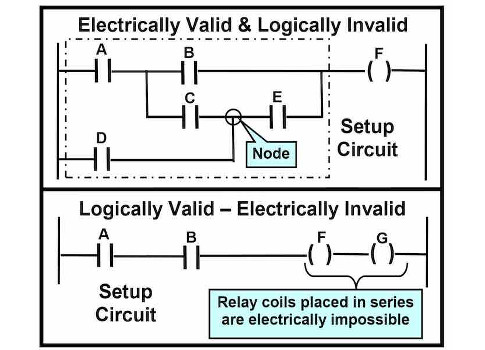
It will be represented with an examine off bit. Introduction to plc ladder diagrams. A programmable logic controller plc or programmable controller is an industrial digital computer which has been ruggedized and adapted for the control of manufacturing processes such as assembly lines or robotic devices or any activity that requires high reliability ease of programming and process fault diagnosis. A wiring diagram is. Wiring diagrams wiring diagrams show components mounted in their general location with connecting wires. Basic plc program for control of a three phase ac motor for beginners on photo.
So when you are building an automation system or a machine you cannot use a plc for the safety related parts of the machine. When including a plc in the ladder diagram still remains. Lets start converting our simple wiring diagram to the plc program in a step by step format. In this circuit the lamp will remain lit so long as any of the pushbuttons remain unactuated unpressed. Schematics are generally easier to read and understand than wiring diagrams.
Gallery of Plc Control Circuit Diagram