After motor started the motor feeder will send the run feedback to the plc. This motor control application can also be accomplished with a plc.

Plc Aneka Listrik
Plc to motor wiring diagram. It will be represented with an examine off bit. This figure shows the e stop wired to cutoff power to all of the devices in the circuit including the plc. Above figure does not show limit switch because it depends on external interlock like say level switch flow switch pressure switch etc depending on application. A wiring diagram is a simplified conventional photographic representation of an electric circuit. How to place symbols. When including a plc in the ladder diagram still remains.
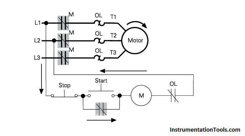
In the following example a normally open start pushbutton is wired to the first input i00 a normally closed stop pushbutton is wired to the second input i01 and normally closed overload relay contacts part of the motor starter are connected to the third input i02. Source of voltage for input to plc applies source of voltage dc 24 volt. To phrase it in a popular way you can say that there are 10 things you need to know in order to draw a wiring or power control circuit diagram quickly and effectively in pcschematic automation. It shows the elements of the circuit as streamlined shapes as well as the power as well as signal connections in between the tools. It uses three contactors an overload relay one auxiliary contact block a normally open start pushbutton a normally closed stop pushbutton an on delay timer of 0 20 seconds and a power supply with a fuse. The run feedback will be displayed on the graphics.
Example of wiring diagram plc following way tacking on the cable. Block diagram of a. Entire system layout fig. Lets start converting our simple wiring diagram to the plc program in a step by step format. But it does tend to become more complex. Just like on the diagram we start with the stop push button.
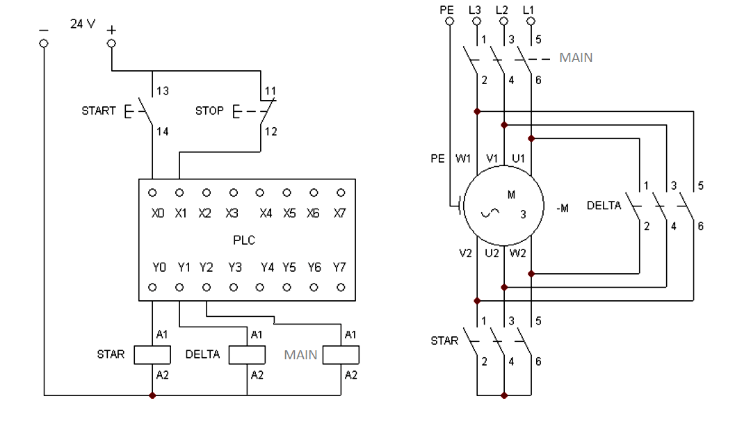
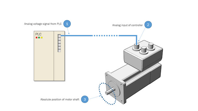
The following diagram is shown for 3 phase motor control of a delta star connection. Assortment of plc panel wiring diagram pdf. The first thing you need to know is how to place symbols in a diagram page in the software. In the case of 3 phase ac operation the most widely used motor is the 3 phase induction motor as this type of motor does not require any starting device being a self starting motor. Im using the siemens tia portal as the plc programming software. In some plcs or in safety plcs if the run feedback is not received in specified time frame say within 5 seconds then plc automatically sends an stop signals to the motor feeder.
These look like a normally closed nc contact. The above figure shows the physical layout of motor starter however this would be designed through ladder logic in this plc tutorial. An electrical motor is an electromechanical device that converts electrical energy into mechanical energy. Figure 5 below shows a schematic diagram for a plc based motor control system similar to the previous motor control example. Wye delta open transition 3 phase motors. Example of wiring diagram for part of input plc input plc applied is limit switch and proximity swtich while plc applied by plc keyence.
If interlock not required then simply remove the symbol from the diagram and connect with simple.
Gallery of Plc To Motor Wiring Diagram


.png)