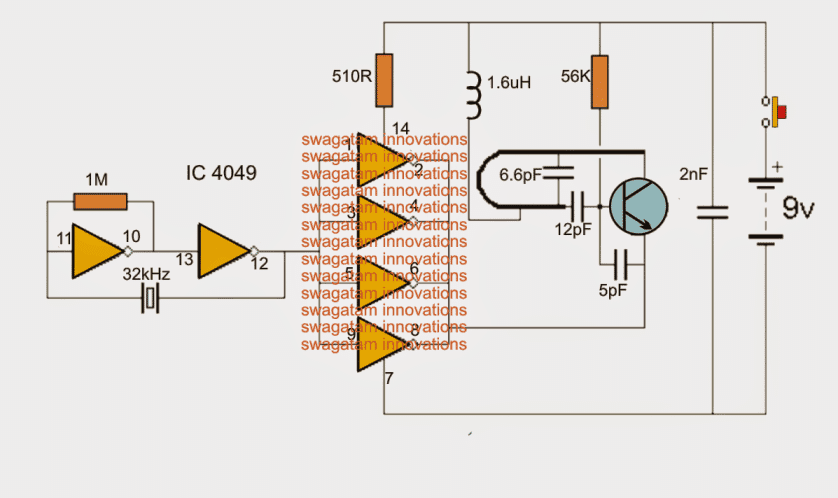
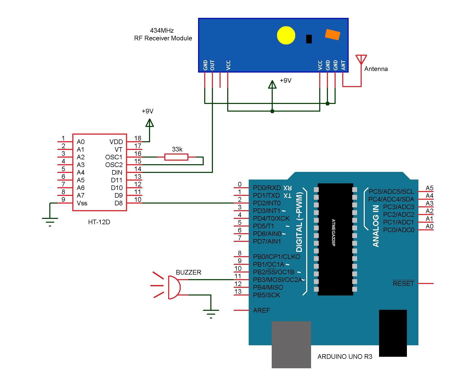
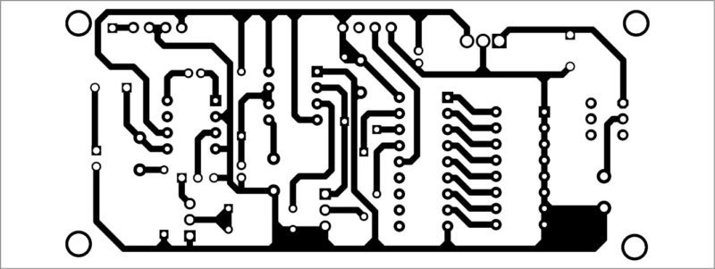
Wireless rf doorbells or remote control doorbells are very common now days they can also be used as wireless calling bells. The circuit shown in fig.
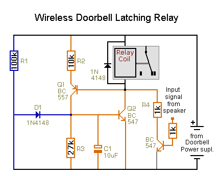
Wireless Doorbell Diagram Amp Page 2 Of Rpwl4045a Doorbell Push
Wireless doorbell calling system circuit diagram. Among electronics students and hobbyists doorbell circuit project is quite popular. Connect the input wires on the transformer to the source circuit using the black to black white to white and ground to green method. The wireless doorbell implemented in this project is just a demonstration of the idea. A doorbell extender simply allows you to extend the reach of your existing door chime so youll never miss the doorbell again. Doorbell is a very common and useful device used in every household. Wiring for two doors is the same as for one with the transformer hardwired to the 120 volt source from a house circuit.
The wireless doorbell transmitter and receiver circuit are incorporated below. But the idea can be extended to actual real time wireless doorbell system. The main feature of this doorbell is that we can control the time duration for which it keeps ringing upon pressing the. All transistors are 2n3563 the u shape coil is a single half turn using a 1mm copper wire with 5mm diameter the most fundamental constituent is the transistor. Wiring diagram for a two chime doorbell. 1 provides a mechanical means of striking two gongs or chimes in sequence one when the doorbell is pressed the other when it is released.
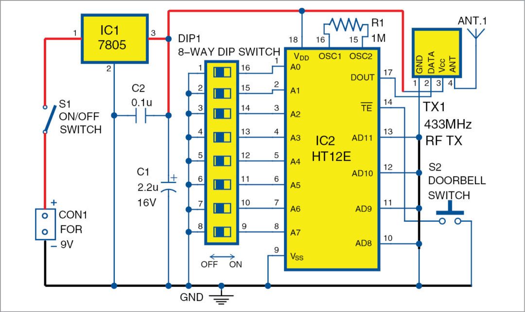
Transmitter this transmitter section is designed around oscillator transistor bf194b t 2 followed by two transistor bc148 t 1 and t 3. Video pedia 16539 views. Wireless doorbell the transmitter circuit is made up of two building blocks the 303mhz rf oscillator and the 32khz crystal controlled oscillator. Since the mode of communication is rf the range is considerably large that other wireless technologies. All 4 bit data pins ad8 through ad11 are connected to ground to reduce power consumption because 433mhz rf transmitter module tx1 uses on off key ook modulation. Electronic project diy circuit ideas doorbell calling bell using ht 2811 with circuit diagram duration.
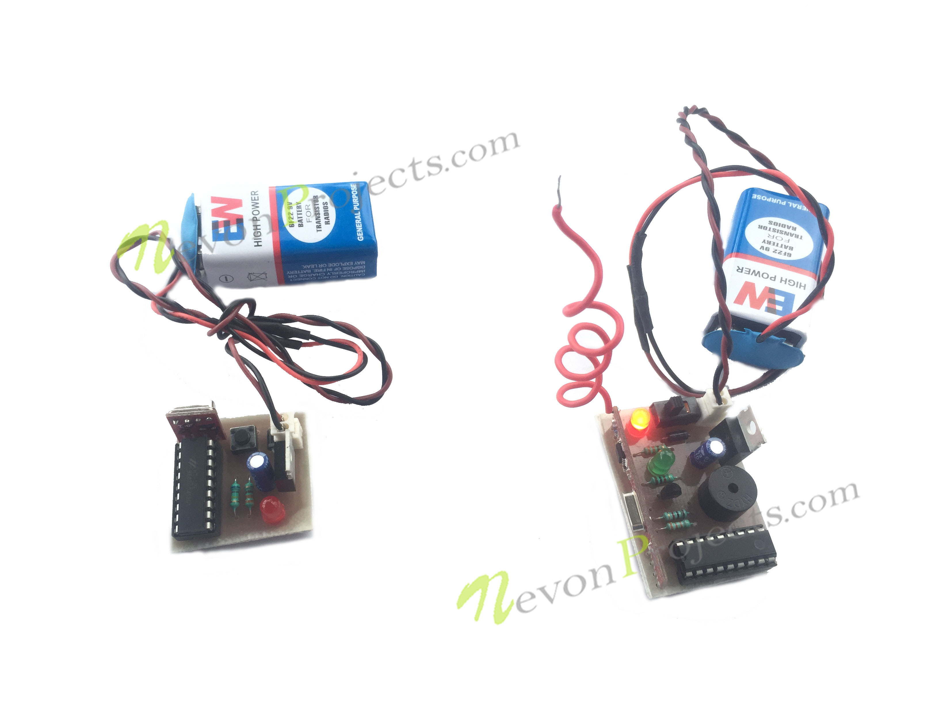
So in this tutorial we are going to build a doorbell with 555 timer ic. Circuit diagram of transmitter unit for the wireless doorbell dip1 is used to set the address bit either high or low. As the wireless doorbell is wireless based project it is divided into two major section ie. Every rf wireless bell is consist of two parts which are a rf transmitter remote control and a receiver with a music or alarm generator. A wireless doorbell works by transmitting a signal to the chime box eliminating the need for a wired connection.

