Here is a picture gallery about inductive proximity sensor wiring diagram complete with the description of the image please find the image you need. Inductive proximity switch as limit switch for cnc connection and selection of pull down resistor duration.

120v 3 Wire Prox Switch Wiring Diagram Trailler Bugati17
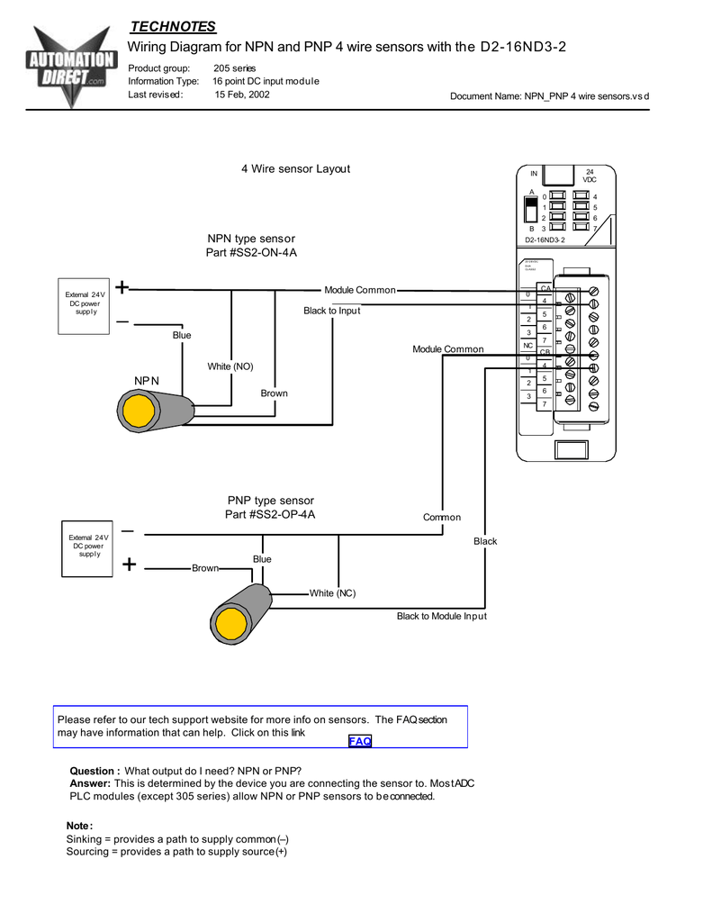
Proximity switch connection diagram. If its a short connection and not too noisy an environment just use a small signal npn transistor with a base resistor 10k should work nicely and a pullup to 5v on the collector and run the collector to your micro input. Isko distance sensor bhi bol sakte hai kyonki ye switch jab target ek distance par iske front me hoga to iska contact. A wiring diagram is a streamlined standard photographic depiction of an electrical circuit. Pic how to connect a inductive proximity sensor switch npn dc6 pertaining to inductive proximity sensor wiring diagram image size 786 x 498 px and to view image details please click the image. Either the load is connected to negative and the positive is switched pnp continue reading an easy way to remember pnp and npn sensor. With the sensor the op stated they have now the digital signal to the micro will be high when metal is detected low when.
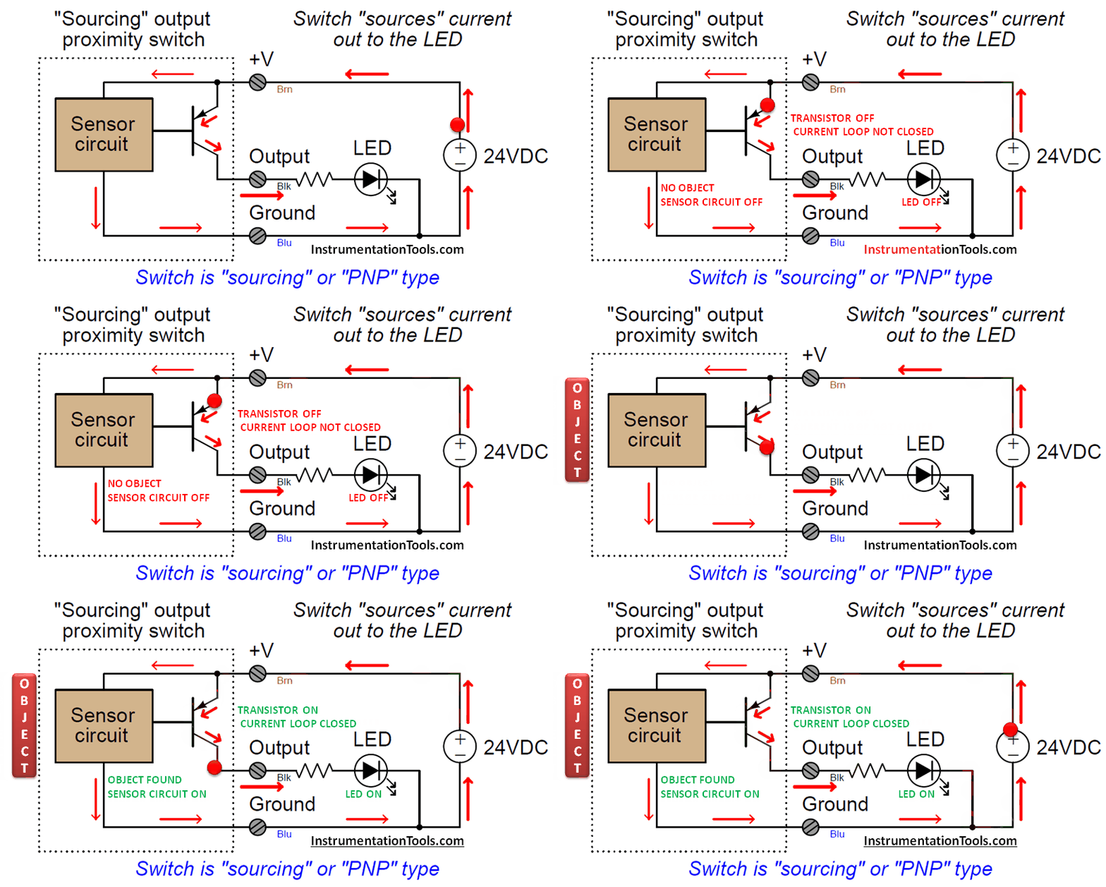
Redwhite inductive cylindrical 2 wire ac acdc inductive proximity sensors 2 wire ac and acdc 110 singapore. Hello dosto aaj ki is video me hum proximity switch ke baare me sikhenge. Pnp switched positive npn switched negative switched refers to which side of the controlled load relay small indicator plc input is being switched electrically. Connecting a proximity sensor to a plc can be a daunting task at first glance. Diagram duration. Martin barfoed 41271 views.
The first step is understanding how plc networks are set up. It shows the components of the circuit as streamlined shapes and also the power as well as signal connections in between the devices. The process varies depending on the sensor and input module used in the configuration. A polarized option requires the power wire to be connected to the positive side and the ground wire to be connected to the negative side of the power supply. A 2 wire sensor of course only has 2 wires including a power wire and ground wire with connection options of polarized and non polarized. This circuit is for an unusually sensitive and stable proximity alarm which may be built at very low cost.
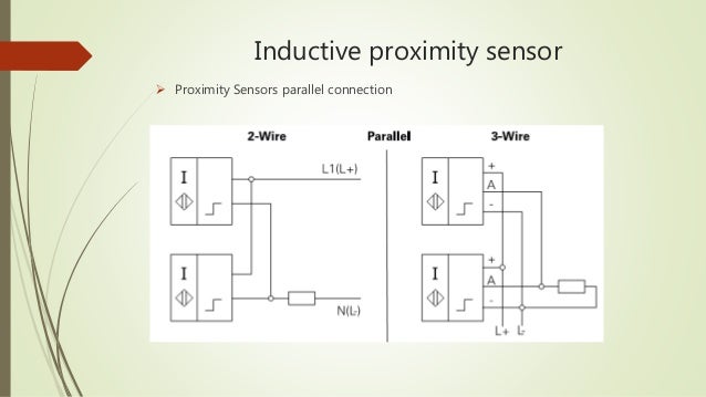
Collection of 2 wire proximity sensor wiring diagram. For one thing there is no universal way to connect proximity sensors. The four major components of a. Heres a simple way remember how to wire up a 3 wire dc pnp or npn sensor.

