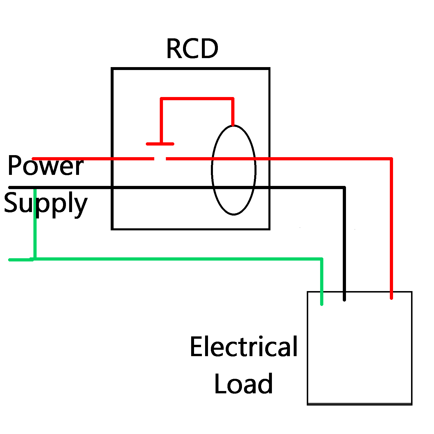
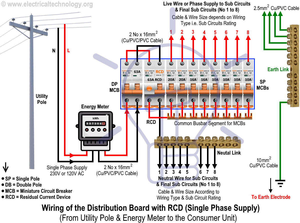
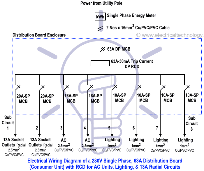
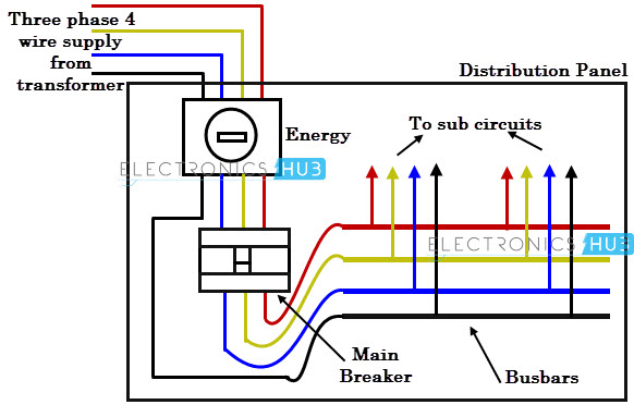
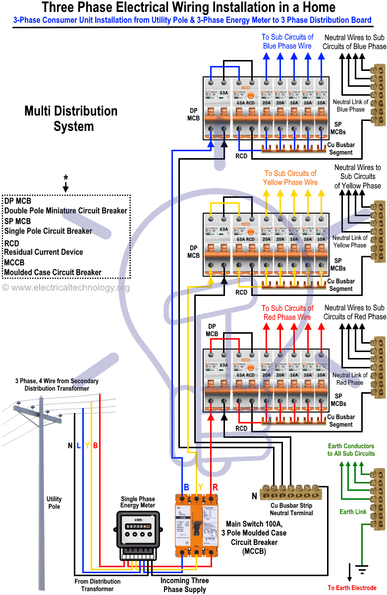
A wiring diagram is a simple visual representation of the physical connections and physical layout of an electrical system or circuit. In the above distribution diagram i shown the wiring installation of double pole mcb circuit breaker rcd circuit breaker single pole mcb breakers voltmeter light indicator.

Electricity Hazards 10th Physics Lesson 16 8 Part 2
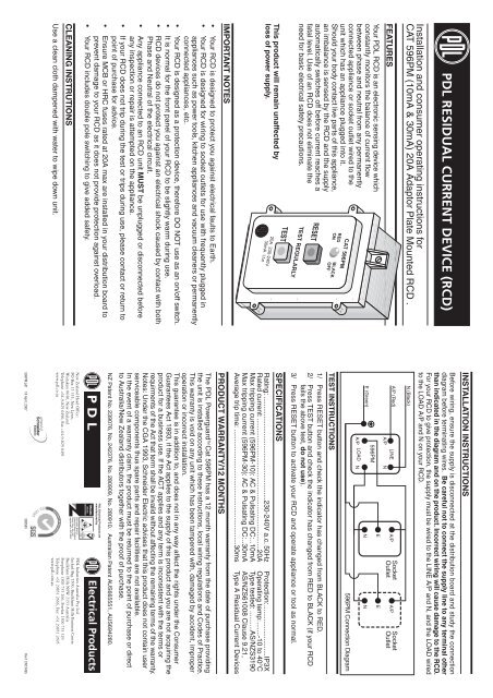
Rcd wiring diagram australia. It shows how the electrical wires are interconnected and can also show where fixtures and components may be connected to the system. How to wire rcd residual current device. Here is the rcd wiring diagram in which i install the main distribution board. Demand of these three circuits must not exceed rating of rcd ol n n n a neutral link do not earth ol clipsal rcd 2 4n 1 3n a mains switch a e n n an. This can be overcome by installing a resistor between the load side neutral terminal and load side phase that supplies the trip button circuit see wiring diagram below. Inspection of the switchboard is not part of a pre purchase building inspection as per our australian.
The installation of rcd is too simple in single phase wiring main board. In this single phase home supply wiring diagram the main supply single phase live red wire and neutral black wire comes from the secondary of the transformer 3 phase 4 wire star system to the single phase energy meter note that single phase supply is 230v ac and 120v ac in usthese two lines line and neutral from energy meter are. Clipsal rc and 4rc series residual current device wiring diagrams 1 2 main switch single phase e 3n 4n clipsal rcbm 4rcbm and 4rcbe series combined mcbrcd wiring diagram a warning combined max. A rcd will still function without a neutral connection however the test button will not operate. Just a view of the inside backing board of a domestic switch board here in sydney australia.
