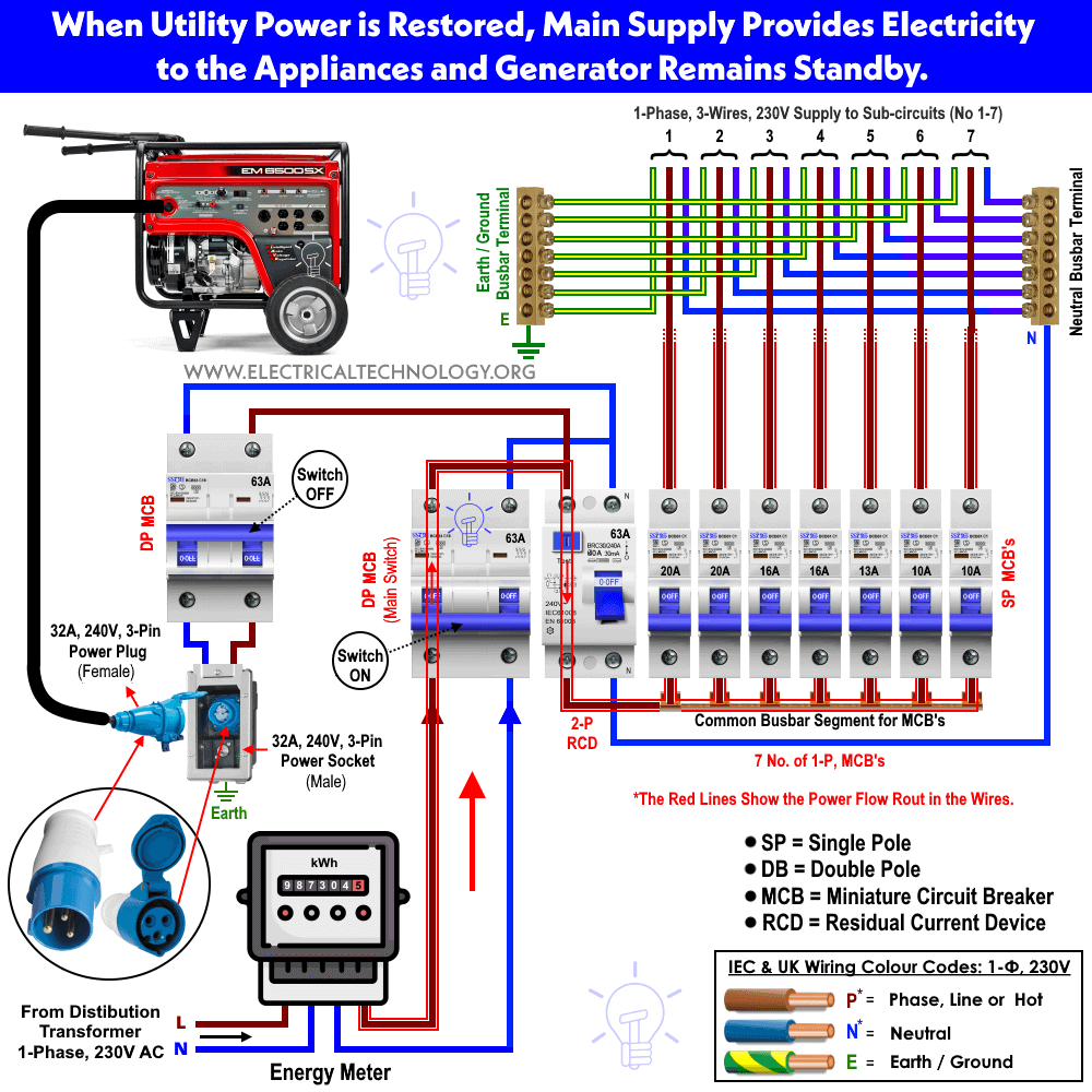
Wiring of the distribution board with rcd single phase from energy meter to the main distribution board fuse board connection electrical technology domestic switchboard wiring diagram nz this is how the connections to be done inside the consumer unit red denotes the domestic switchboard wiring diagram nz. Gsh electrical 72071 views.

Bx 3650 Domestic Switchboard Wiring Diagram Australia
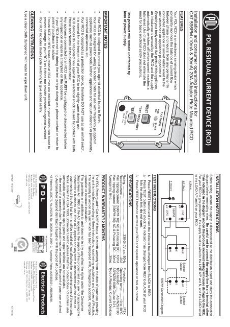
Rcd wiring diagram nz. Press the test button. How to wire rcd residual current device. Our led downlight tool will help you find the most energy and cost efficient lights for your needs. If the appliance turns off the rcd is working. You can test your socket outlet and portable rcds by plugging in a small electrical appliance such as a night light. Start calculating your savings.
Find out how to wire rcds in split consumer unit. It shows how the electrical wires are interconnected and can also show where fixtures and components may be connected to the system. If you look at the circuit diagram i posted in option 2 the neutral to each socket or sockets protected by a miniature circuit breaker comes from the rcd neutral bus not the main neutral bus which will be used for other supplies such as cooker air conditioning etc etc. A wiring diagram is a simple visual representation of the physical connections and physical layout of an electrical system or circuit. Garageshed consumer unit. Demand of these three circuits must not exceed rating of rcd ol n n n a neutral link do not earth ol clipsal rcd 2 4n 1 3n a mains switch a e n n an.
More electrical tips and diagrams wwwaboutelectricitycouk like subscribe and dont skip the ads shopping list. If the neutrals to these sockets run back to the main neutral bus then the rcd is not in circuit doing anything. They will provide protection for all electrical wiring and appliances plugged into new circuits. Understanding your consumer unit layout identifying conductors spds mcbs and rcds fuse box duration. Highly reliable and flexible our industrial switchgear is your perfect choice for your industrial applications. Clipsal rc and 4rc series residual current device wiring diagrams 1 2 main switch single phase e 3n 4n clipsal rcbm 4rcbm and 4rcbe series combined mcbrcd wiring diagram a warning combined max.
In this single phase home supply wiring diagram the main supply single phase live red wire and neutral black wire comes from the secondary of the transformer 3 phase 4 wire star system to the single phase energy meter note that single phase supply is 230v ac and 120v ac in usthese two lines line and neutral from energy meter are.


