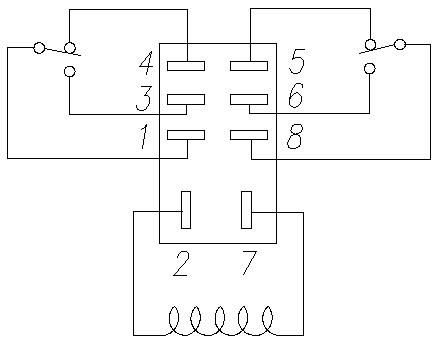
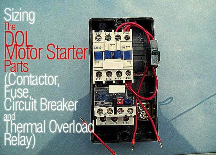
Magnetic contactor circuit diagram luxury thermal overload relay. The tesys k range contactors lc1k and tesys lr overloads lr2k have additional pins on their overloads to make direct connection to terminals 14 on contactor to 95 on overload and a2 on contactor to 96 on overload.

Relay Contactor Wiring Diagram Wiring Diagram
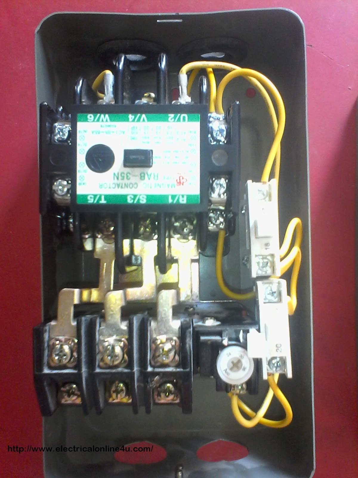
Relay contactor connection diagram. Contactor wiring and i hope after this post you will be able to wire a 3 phase motor i also published a post about 3 phase motor wiring with magnetic contactor and thermal overload relay but today post and contactor wiring diagram is too simple and easy to learn. Contactor wiring diagram pdf download furnas contactor wiring diagram download. Contactor switching time is higher than relay. The wiring diagram of an overload relay is shown below and the connections of an overload relay symbol may seem like two opposite question marks otherwise like s symbol. Many large pieces of equipment are powered directly from high voltage lines. A simple circuit diagram either of the two start buttons will close the contactor either of the stop buttons will open the contactor.
Overload relay connection diagram. How to wire a contactor. These diagrams do not relate to such systems unless the 2 right hand pins are first removed. Note that one one of the contactor acts as a switch for the start button. Contactor vs relay applications. Its is important to.
Dol starter control and power wiring by using a fuse contactor overload relay motor. Contactor working principle of contactor is same as relay but it mainly uses for heavy duty work. Easy and simple wiring diagram to make you learn easily watch the video and subscribe my youtube channel air. There are many type of button as momentary switch selector switch. Although there are several types of overload relays available in the market however the most frequent type of relay is the. Working diagram of relay.
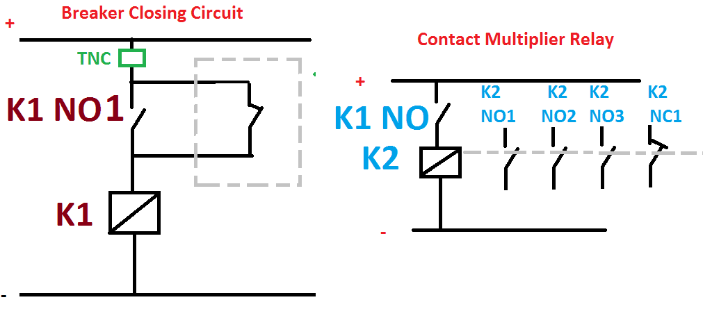
These lines far exceed the 120 volts ac standard in most homes. Lighting contactor wiring diagram with cell westmagazine net. Switch this element uses for interface between machine and human or operator. The overload relay workingfunction is discussed below. 240 volts ac and 480 volts ac are commonly used for these large pieces of. A contactor joins 2 poles together without a common circuit between them while a relay has a common contact that connects to a neutral position.
Contactors are typically built for and used in 3 phase applications where a relay is more commonly used in single phase applications. Iec contactor wiring diagram bureaucraticallyfo. 2 days ago i wired 380 to 440 volts contactor for a 3 phase motor and save these images of contactor in pc. Friends ye video bahut important video hai because is video me ham practically janne wale hai ki ak contactor ke connection kaise kiye jaate hai to aap is video ko poora jarur dekhiyega taki apke.


