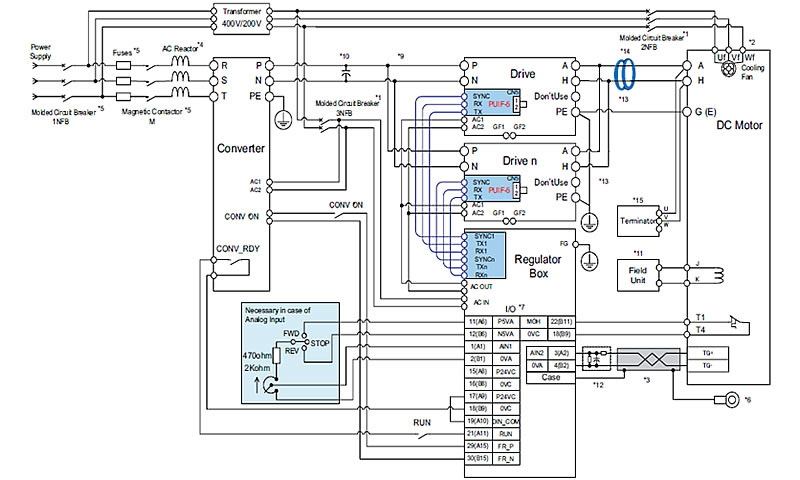
The reliance dc i controller is available housed in its own. Now for the purposes.
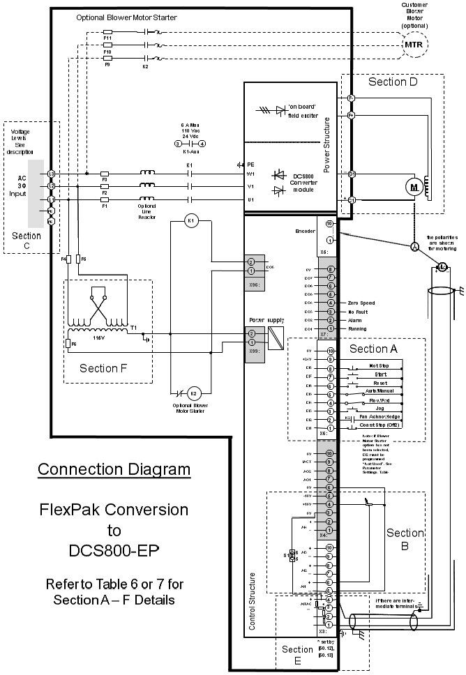
Reliance Motor Wiring Diagram C3 Wiring Diagram
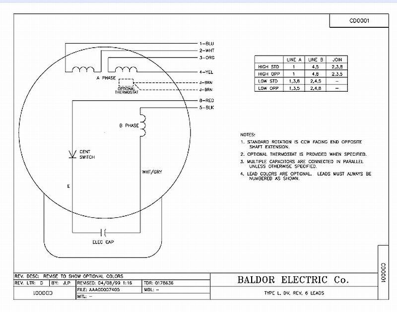
Reliance dc motor wiring diagram. These connections are in accordance with nema mg 1 and american standards publication 06. Baldor reliance industrial motor wiring diagram new wirh baldor. Baldor motor wiring diagram baldor 5hp motor wiring diagram baldor brake motor wiring diagram baldor dc motor wiring diagram every electrical structure is composed of various diverse parts. Refer to mn408 for additional details on lead marking. Specifically performance matched to the reliance dc i permanent magnet motor to provide the most compact and economical controllermotor package. If not the arrangement will not function as it should be.
How to wire a baldor 3 phase motor. Each component should be set and connected with different parts in particular way. 57 719 32 132 35 157. Use figure 1 if your motor has a single voltage shunt field. Wiring a baldor motor can at first glance look to be a very intimidating task. Achieve the next level of energy efficiency with abbs new baldor reliance ec titanium integrated motor drive press release motor standards have been in place for decades yet there is a growing demand to achieve greater efficiencies as regulations continue to tighten on the total system for fans pumps and compressors.
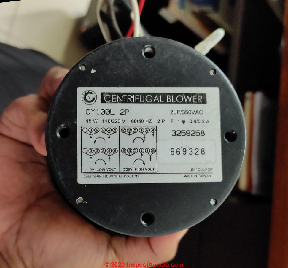
Yet with the help of this step by step guide this task will be become as easy as counting to five. Motor wiring diagram dc. 5 hp electric motor single phase wiring diagram beautiful single. Baldor single phase motor wiring diagram collections of weg motor capacitor wiring diagrams schematics and baldor diagram in. Motor connections your motor will be internally connected according to one of the diagrams shown below. Use the typical interconnection diagram figure 1 as refer ence throughout this installation procedure.
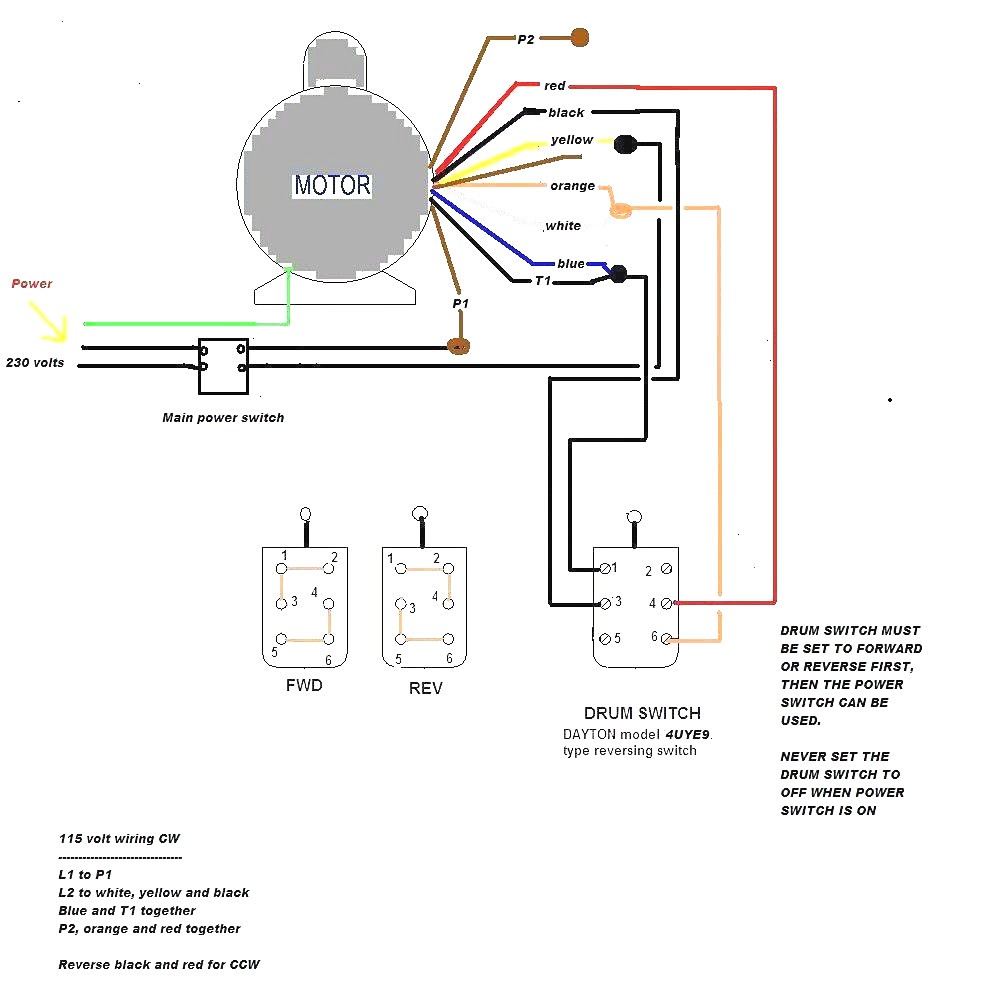
Weg motor capacitor wiring diagrams schematics and baldor diagram in. Use figure 2 if your motor has a dual voltage shunt field. The wiring fusing and grounding must comply with the national electrical code. Wiring connect the motor as shown in the connection diagrams. If this motor is installed as part of a motor control drive system connect and protect the motor according to the control manufacturers diagrams.





.png)
