The book describes in simple words and drawings the basic principles to make generator control panels. Nameplate gives the maximum input current as 25a the circuit breaker should be rated at least 30a.

China Ats Wiring Diagram For Standby Generator 50 Amp Auto
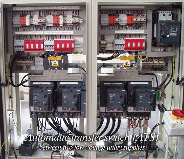
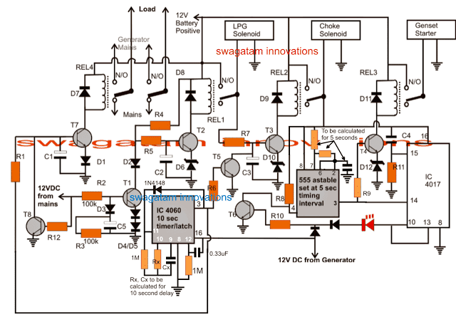
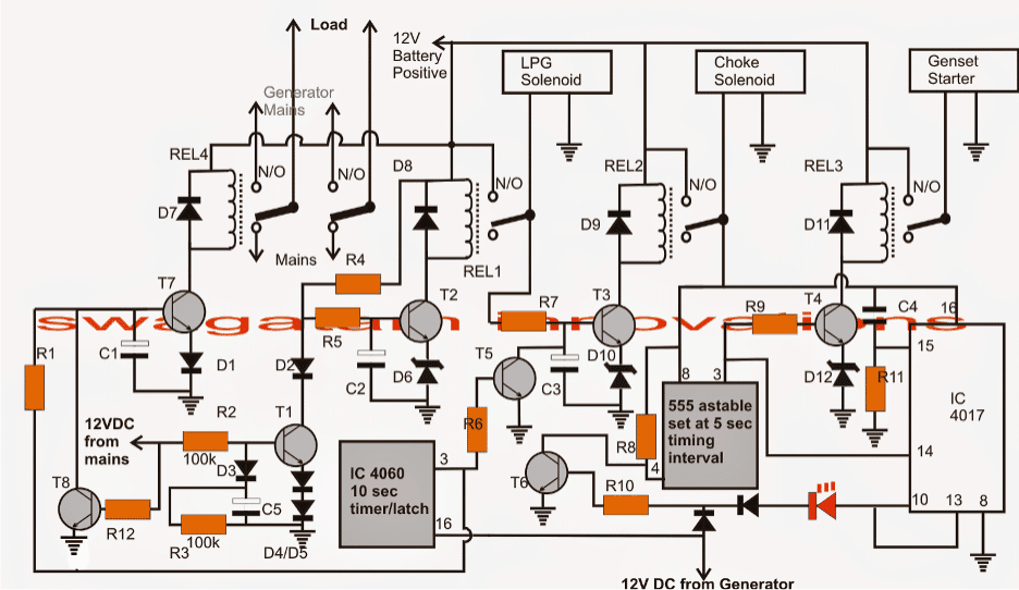
Circuit diagram of ats. Learn how to make automatic transfer switch panels. A wiring diagram is a simplified conventional photographic depiction of an electric circuit. Updated ats circuit diagram with complete ic 4060 and ic 555 wiring details. Ats panel for generator wiring diagram pdf data wiring diagram. Automatic transfer switch diagram. Technical information 3 standard diagrams transfer between 2 sources 1 bus bar.
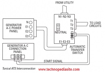
Automatic transfer switch circuit diagram. Ats auto transfer switch power control diagram auto change over power control circuit how to program schneider inverter start up setting of vfd inverter parameter setting bangla. Designed and written by. Hi sir i have one client which the lv switchboard include two number of 500a mccb units as the incoming ats for essential and city main power. Breaker contactor or motorised switch socomec diagram. The guide includes step by step examples in a way that you will be able to make panels in the size 15 up to 200kva.
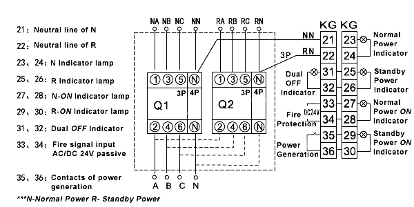
67 astonishing ideas of champion generator wiring diagram diagram. The following article explains an enhanced automatic transfer switch ats circuit which includes several customized sequential changeover relay stages making the system truly smart. Variety of ats wiring diagram for standby generator. Motorised switch cl ncl g q1 q2 ats automatic transfer switch protection arent shown on the following schemes summary. Figure 1 atsgts to ups wiring diagram. 15 schematic circuit diagram for automatic transfer switch 16 recommended cable size 17 specifications 171 general specification.
Part 1 ats automatic transfer switch control and power circuit tutorial tagalog 24 pinoy teknisyan duration. Mar 3 2016 automatic transferred switch ats circuit diagram electrical engineering blog. Pinoy teknisyan 13165 views. If stranded wires are used ferrules or equivalent crimping terminals must be used. During the building power test the auto mode of ats system was not fed to essential power when the city power is. The input and output lines to and from the atsgtsups system must have disconnect devices attached.
Can you kindly pass me the control circuit diagram for ats. This manual should remain with the unit.

