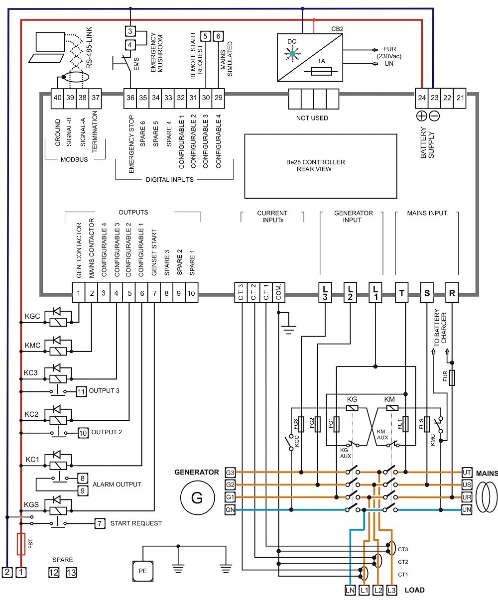
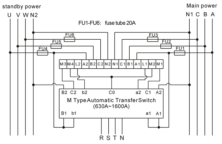
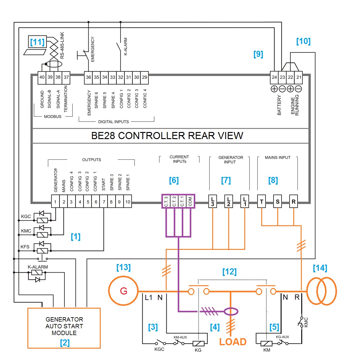
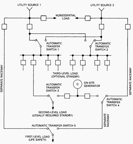
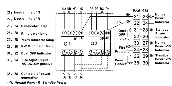
A wiring diagram is a simplified traditional pictorial depiction of an electrical circuit. Amp service entrancenon service entrance automatic transfer switch owners manual.
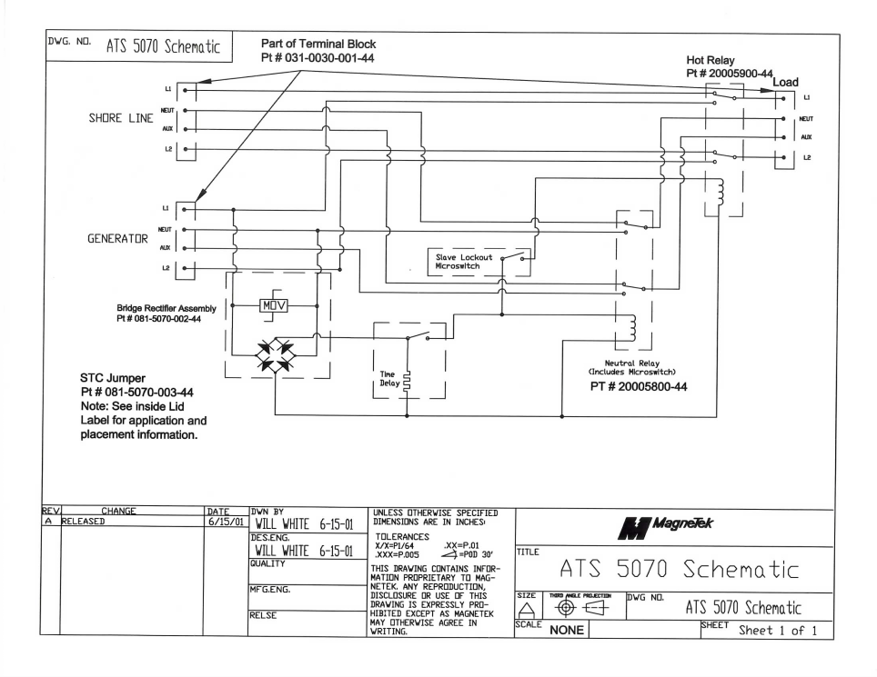
Ats5070 Generator Automatic Transfer Switch
Automatic transfer switch control wiring diagram. 50hz transfer switches with 50 hz transfer switches you can choose to cover every circuit all the time or only essential circuits depending upon the generator with which it is paired. Because it is for an optional standby system the owner designates the circuits to be supplied. Collection of asco transfer switch wiring diagram. Automatic selective circuit transfer switch retrofitted to 200a residential service. It reveals the components of the circuit as simplified forms and also the power and signal links between the gadgets. Wiring diagramschematic a v drawing no.
Begin a retrofit by mounting the selective circuit manual transfer switch next to the service entrance panel photo 2. Transfer switches are reliable rugged versatile and compact assemblies for transferring essential loads and electrical distribution systems from one power source to another. Automatic transfer switches ats are critical components of any emergency or standby power system. Generac 200 amp automatic transfer switch wiring diagram whole house transfer switch wiring diagram fresh generac 200 automatic transfer switch wiring diagram 973 file type. It shows the elements of the circuit as streamlined forms as well as the power as well as signal links in between the devices. These switches figure 11 are used with a single phase system.
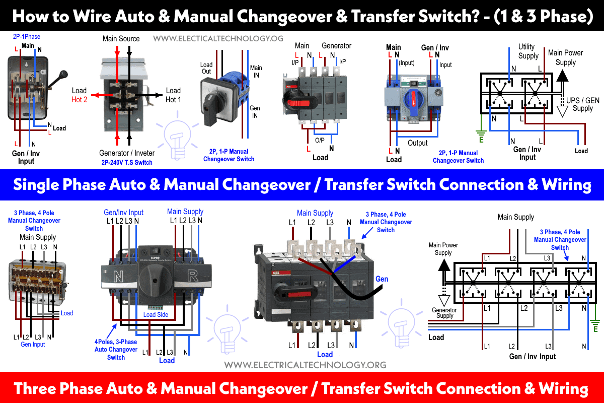
Refer to the smm ownersinstallation manual forvariety of generac amp automatic transfer switch wiring diagram. The new 16 circuit nema 3r rated automatic transfer switch is weather proof and can withstand high winds rain and winter storms. Variety of 200 amp automatic transfer switch wiring diagram. A wiring diagram is a streamlined standard pictorial depiction of an electrical circuit. The transfer switch consists of a transfer mechanism utility service disconnect circuit breaker a control relay fuses ter minal strip and fuse holder for connection of sensing wires. It is also shows the working and operation for different changeover switches wiring connections like single phase manual changeover switch with generator three phase manual transfer switch connection with generator as well as single phase and three phase automatic transfer switches connections to the 1 and 3 phase generators and main fuse board.
A wiring diagram is a simplified conventional photographic representation of an electric circuit. This transfer switch is suitable for use as service equipment. Transfer between 3 sources 2 bus bars continued implementation compacity built in solution plug and play mechanical and electrical interlocking are in build operation only 2 or 3 emergency handles instead of 4 or 5 a motorized switch can be added on the non critical loads for optional disconnection.


