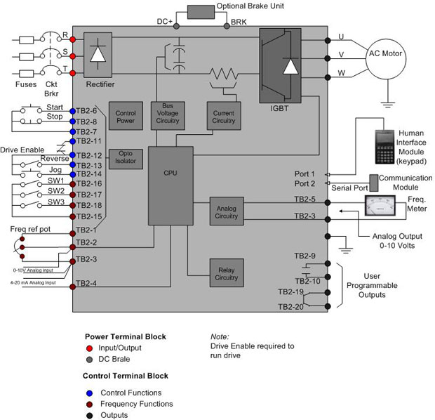
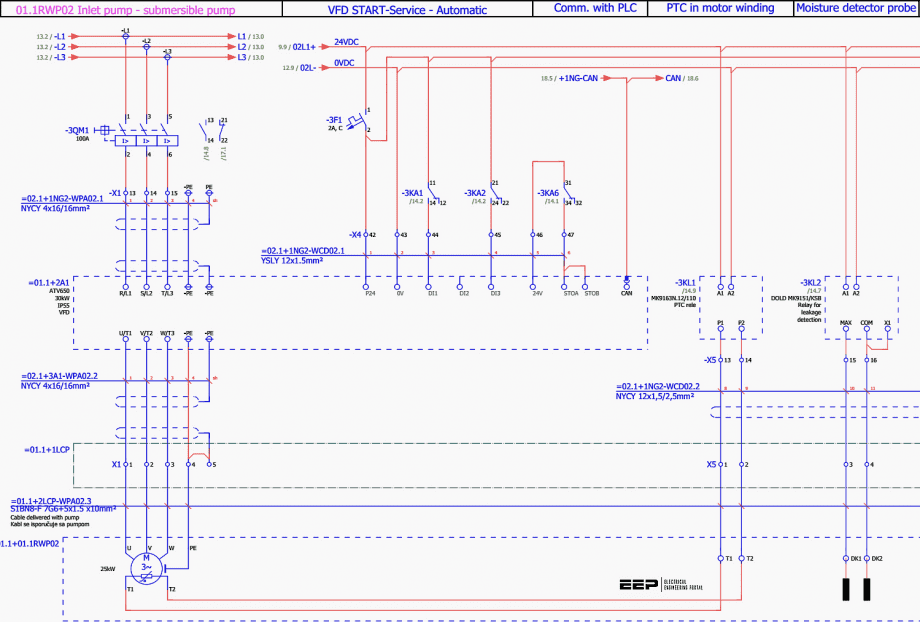
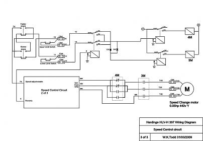
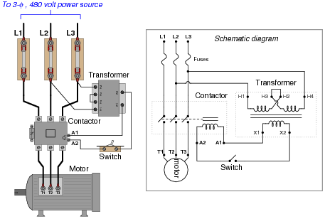
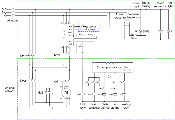
How to wire circuit protection breaker and fuse. Vfd start stop wiring diagram.

Circuit Diagram 3 Phase Motor Forward Reverse H1 Wiring Diagram
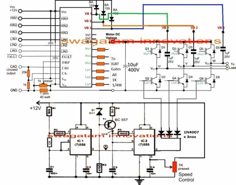
Vfd motor control circuit diagram. Switch on the 3 phase power supply. For programming the vfd m. Frequency control means rpm automatic controlled. Will the nand. Vfd is the short form of a variable frequency drive or adjustable frequency drive. Actually you are the professional at this sectorplease suggest me what i should.
How to control vfd with push button switch terminal control. Vfd is a short form of variable frequency drive or variable voltage variable frequency drivethe vfds are working based on changing the input frequency and input voltage of the motor we can change the speed of the. Different types of vfds are available in the electronics and electrical market ranging from small motor related applications to the high power induction motors. Check connections of l1 l2 l3. Controlling a digital keypad on delta vfd m steps for complete motor control. Thanks sir actually i want to make your vfd circuit.
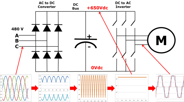
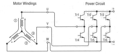
Pin out connection diagram for vfd m fig. The third block of the vfd is called the inverter section because this is where the dc voltage is turned back into three phase ac voltage. 2 diagram shows an electronic diagram of a gozuk vfd. The frequency determines the motor rpm and by controlling the ac frequency the motor rpm can be controlled. How to wire a 3 phase motor and. By varying the output frequency of the motor from 0 to 50 hz the speed of the motor will change but i do not want to use a battery as a power source for the circuit i just need to get its power from home ac electricity220 vthe speed control of the motor will be by arduino.
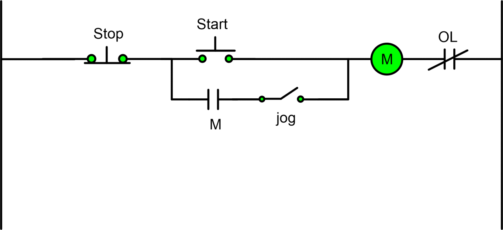
T1 t2 t3 used for giving 3 phase input to vfd and connecting motor to it and wires coming out of m0 m1 and gnd. My induction motor capacity is 05hp 3 phase. The contact in parallel with the run switch is often referred to as a seal in contact because it seals the momentary condition of the run switch closure after that switch is de actuated. That means i want to control 1hz to. The follow up question of how we may make the motor stop running is a. This circuit is known as a latching circuit because it latches in the on state after a momentary action.
Just i want to control frequency of this motor also rpm without any problem. 1 opened variable frequency drive for troubleshooting following fig. The ac induction motor specification 250w 15a 240 v. I am here with giving you a vfd start stop wiring diagram for running a vfd through panel board push button and keypad of the vfd it is called hmi.
