While simple there are numerous variations and enhancements as you will see and the benefits are clearly obvious. In the next episode in this series of videos we will add multiple start stop stations and demonstrate via the onscreen live simulated schematic how they work in the motor control circuit wiring.

Across The Line Starter Electrical Motor Control Wirings
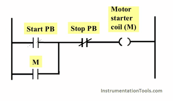
Schematic diagram of a simple start stop motor control circuit. The power source may be either ac or dc and may be at any voltage from 6 to 240v. When you press the start button and the stop button is not pressed the 24vdc relay energizes and it pulls in the r1 contactor that feeds three phase power to the motor. Start stop control wiring diagrams single station basic circuit r 1 klai. 1 j start 2 3 stop i no. The basic language of control is the circuit diagram. They are an ideal means for troubleshooting a circuit.
I zl ii i i ii i i fo 0. They do not indicate the physical relationships of the various components in the controller. Motor start stop a1 a2. Schematic diagrams do not always show both control and motor connections. Vfd is a short form of variable frequency drive or variable voltage variable frequency drivethe vfds are working based on changing the input frequency and input voltage of the motor we can change the speed of the. The circuit will operate as a normal three wire circuit if the start stop pushbuttons are used.
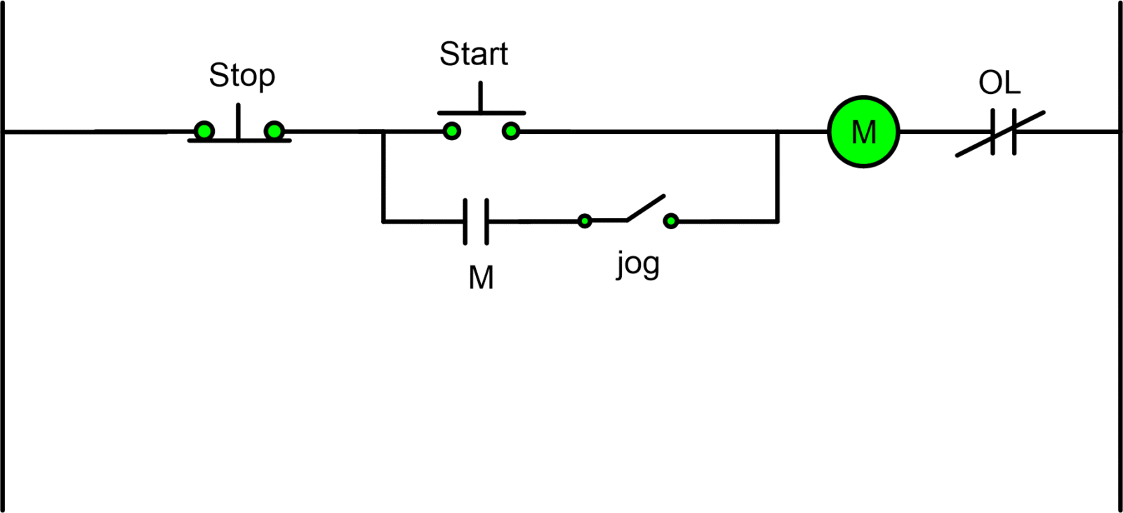
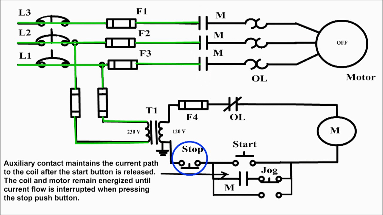
This means the control circuit is designed so there is no way for the load to become energized and stay energized through the memoryseal in contact. Pressing the jog button creates a. The limitation to the first circuit is that the load current flows through the control pushbuttons. The first circuit to be discussed is a basic control circuit used throughout industry. Depressing the stop button breaks the circuit de energizing. I am here with giving you a vfd start stop wiring diagram for running a vfd through panel board push button and keypad of the vfd it is called hmi.
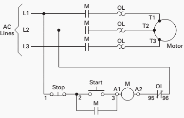
Many schematic diagrams show only the control circuit. Typical line or schematic diagram t3 95 reset 96 l2 t2 l1 1 3 2 t1 97 98 3 2 1 m ol 3 phase motor start stop a1 a2 l3 t3 95 ol ol ol ol 96 l2 t2 l1 1 2 3 t1 ac. Figure 914 shows a start stop push button circuit. For more information visit. One of the jog circuit designs is the two circuit pushbutton. A very common form of latch circuit is the simple start stop relay circuit used for motor controls whereby a pair of momentary contact pushbutton switches control the operation of an electric motor.
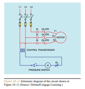
This schematic shows both the control circuit and the motor circuit. In this particular case i show a low voltage control circuit and a 3 phase higher voltage motor. The most common use of 3 wire control is a startstop control. Figure 2 shows a typical line or schematic diagram. I operation depressing the start button energizes coil m hold in contacts m and maintains the circuit after the start button is released. Line diagrams also called schematic or elementary diagrams show the circuits which form the basic operation of the controller.
Vfd start stop wiring diagram. See image below for an example of 3 wire control being used to pull in a contactor to start a 3 phase motor.
Gallery of Schematic Diagram Of A Simple Start Stop Motor Control Circuit