We could replace the push button switches with. The circuit will operate as a normal three wire circuit if the start stop pushbuttons are used.
3 Phase Wiring Question Start Stop Switch The Home Machinist
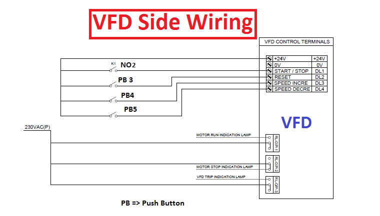
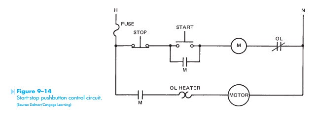
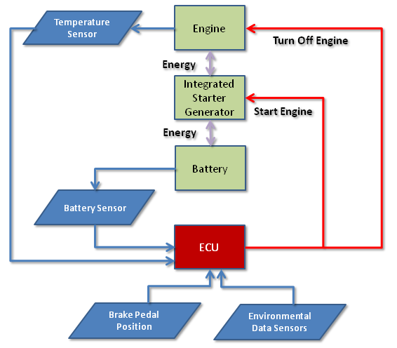
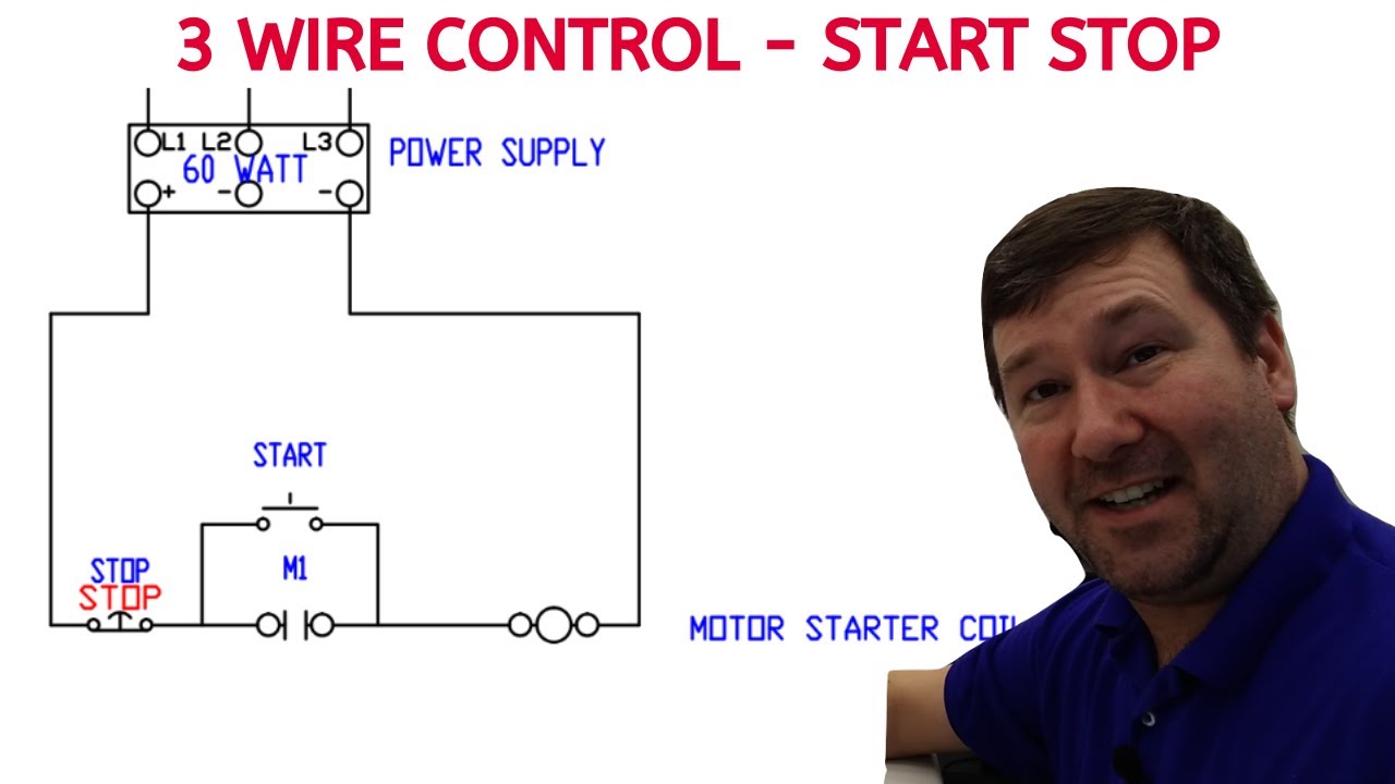
Schematic diagram start stop motor control circuit. Vfd is a short form of variable frequency drive or variable voltage variable frequency drivethe vfds are working based on changing the input frequency and input voltage of the motor we can change the speed of the. Figure 914 shows a start stop push button circuit. When you press the start button and the stop button is not pressed the 24vdc relay energizes and it pulls in the r1 contactor that feeds three phase power to the motor. A very common form of latch circuit is the simple start stop relay circuit used for motor controls whereby a pair of momentary contact pushbutton switches control the operation of an electric motor. The power source may be either ac or dc and may be at any voltage from 6 to 240v. See image below for an example of 3 wire control being used to pull in a contactor to start a 3 phase motor.
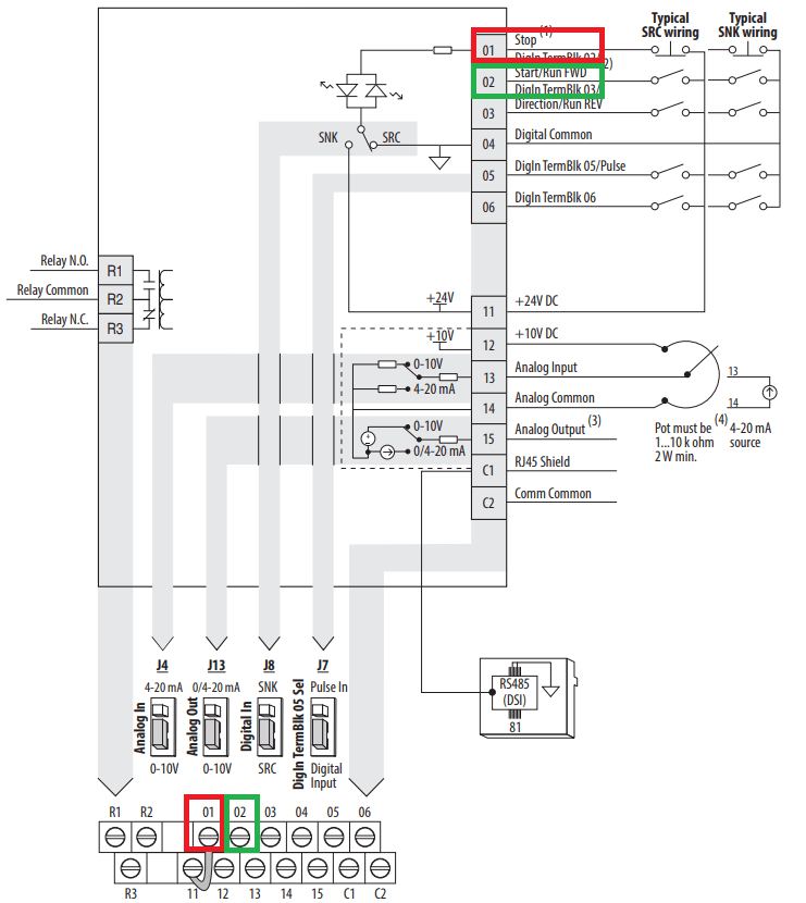
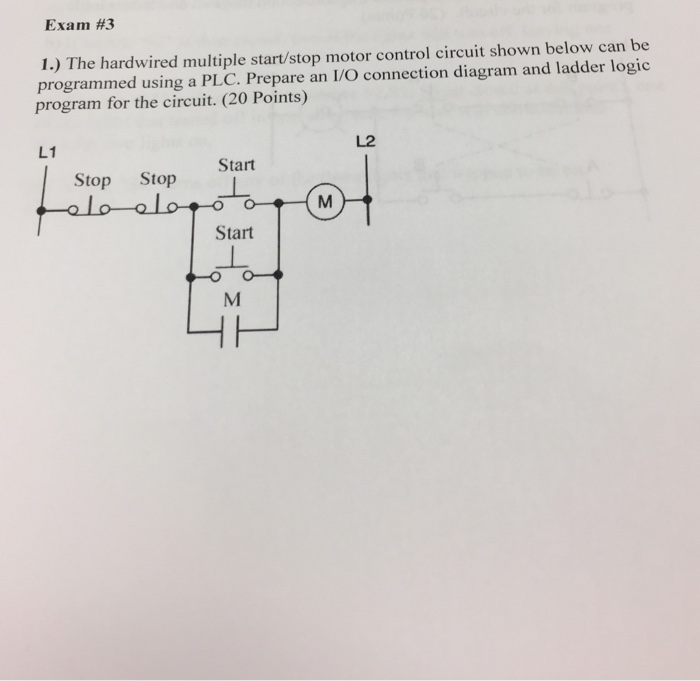
Depressing the stop button breaks the circuit de energizing. Pressing the jog button creates a. I operation depressing the start button energizes coil m hold in contacts m and maintains the circuit after the start button is released. 1 j start 2 3 stop i no. Vfd start stop wiring diagram. This video builds on the standard 3 wire circuit by incorporating multiple stopstart stations.
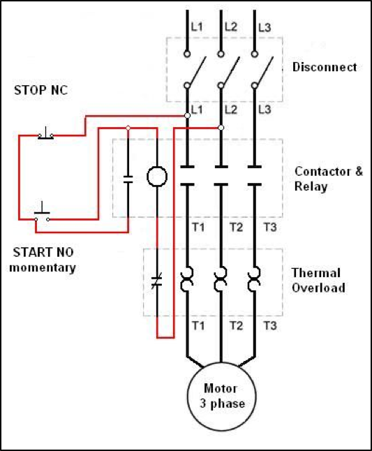
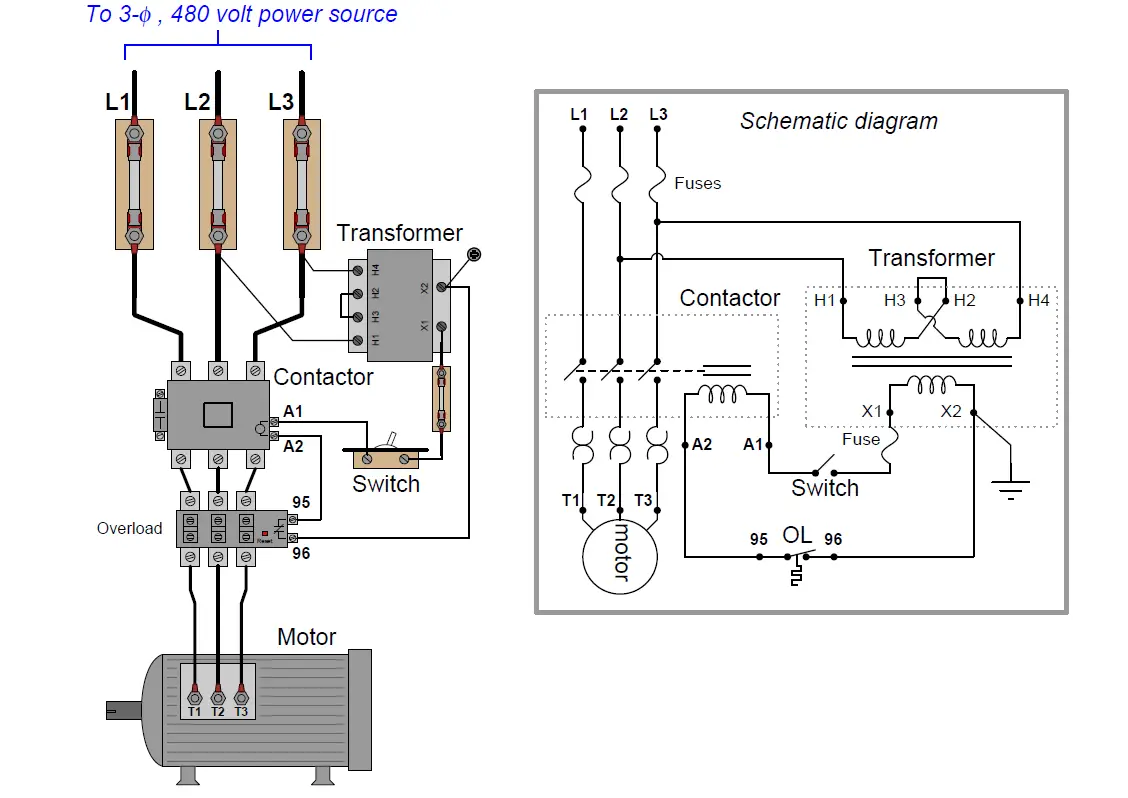
Start stop control wiring diagrams single station basic circuit r 1 klai. Ladder diagram basics 3c 3 wire control duration. This schematic shows both the control circuit and the motor circuit. This means the control circuit is designed so there is no way for the load to become energized and stay energized through the memoryseal in contact. Many schematic diagrams show only the control circuit. The most common use of 3 wire control is a startstop control.
The first circuit to be discussed is a basic control circuit used throughout industry. The limitation to the first circuit is that the load current flows through the control pushbuttons. Schematic diagrams do not always show both control and motor connections. I zl ii i i ii i i fo 0. In this particular case i show a low voltage control circuit and a 3 phase higher voltage motor. I am here with giving you a vfd start stop wiring diagram for running a vfd through panel board push button and keypad of the vfd it is called hmi.
The interlock contacts installed in the previous sections motor control circuit work fine but the motor will run only as long as each push button switch is held down. While this may be perfectly acceptable for low power applications it is not recommended for high power. If we wanted to keep the motor running even after the operator takes his or her hand off the control switches we could change the circuit in a couple of different ways. In the next episode in this series of videos we will add multiple start stop stations and demonstrate via the onscreen live simulated schematic how they work in the motor control circuit wiring. One of the jog circuit designs is the two circuit pushbutton.
Gallery of Schematic Diagram Start Stop Motor Control Circuit