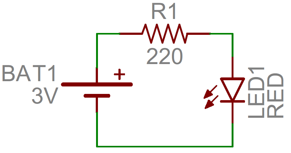
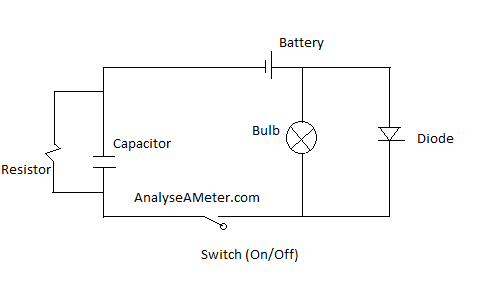
Ether of the dark detecting circuits will work when the solar cell or the photo resistor is in the light q1 is closed reducing the base of q2 to near 0 volts opening the transistor and shutting down the led driver. The circuit diagram for leds in parallel connection is shown in the following image.
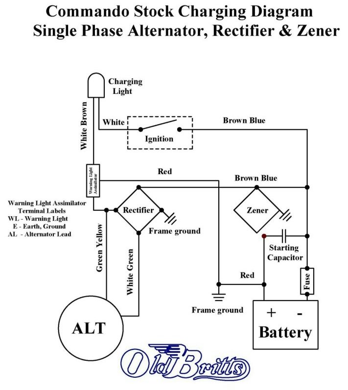
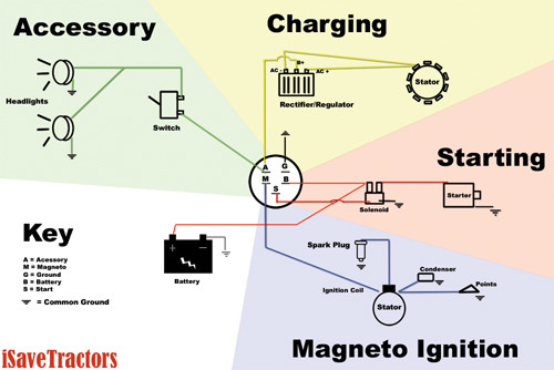
Old Britts Simplified Wiring Diagrams
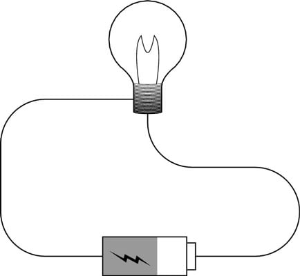
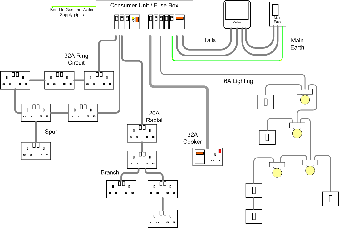
Simple wiring circuit. Wiring diagrams device locations and circuit planning a typical set of house plans shows the electrical symbols that have been located on the floor plan but do not provide any wiring details. Equipment coming off a switchboard or circuit panel should be straightforward to trace. In a circuit electrons flow from the battery through the wires and into the light bulb. 255 time to complete. It shows how the electrical wires are interconnected and can also show where fixtures and components may be connected to the system. This timer circuit uses a 555 ic timer.
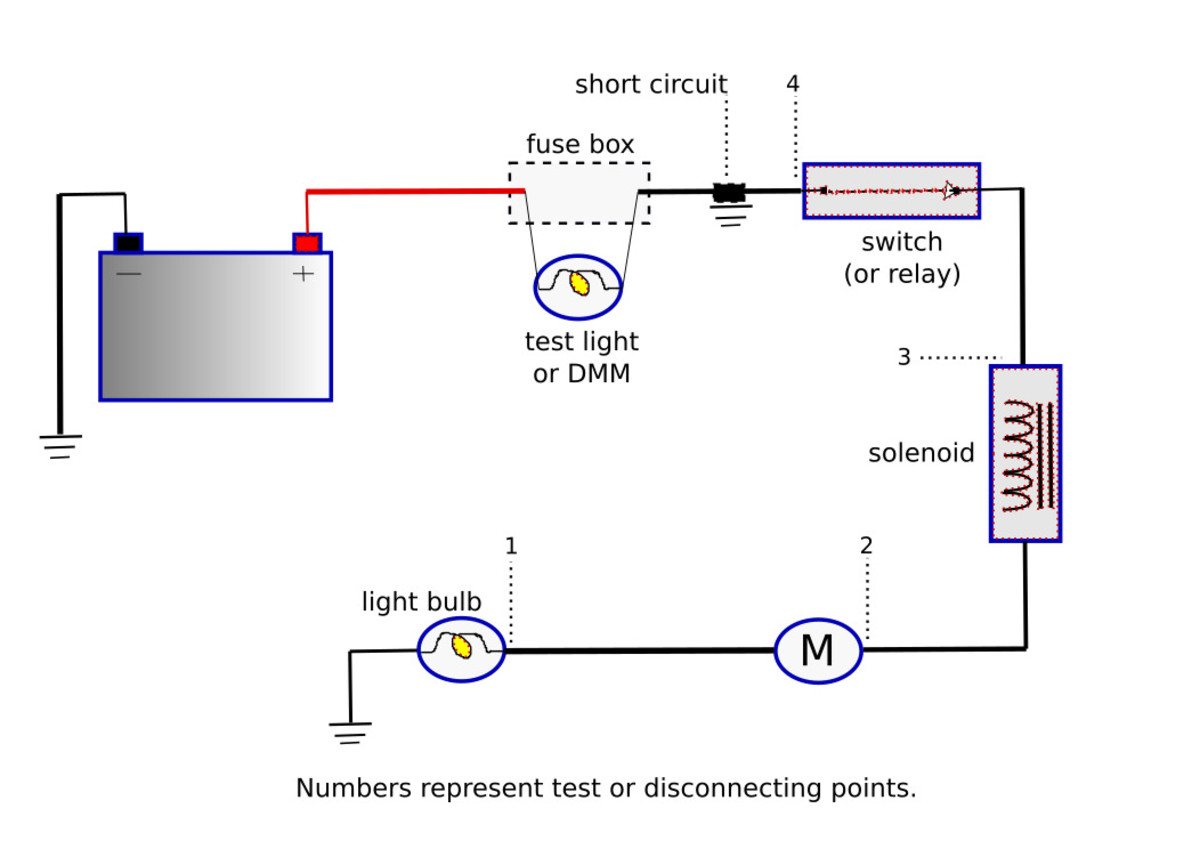
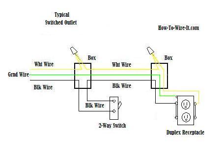
A wiring diagram is a simple visual representation of the physical connections and physical layout of an electrical system or circuit. It doesnt cover the following information which may vary depending on the type of installation you are doing and the type of existing wiring you may be connecting to. In a simple way in circuit use transistors without ic. The current source provides power wiring carries power to the load and the load uses the power. It is up to the electrician to examine the total electrical requirements of the home especially where specific devices are to be located in each area and. I am running the boat battery wiring from the switch to my two batteries.
This is small compact and portable. Electricity flows in a continuous loop from source to load and back again. When you make your own wiring diagram use very large sheets of paper for clarity. Now that you have a 12 volt led driver it is a simple matter of attaching the dark detecting circuit to the led driver. Feb 5 2020 explore elects agass board electrical diagram on pinterest. Simple boat wiring diagram single battery.
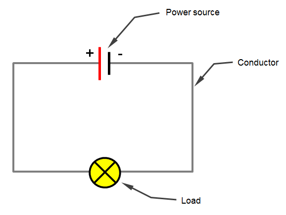
You can hear a sound and show it with an led display. Circuit 3 of simple led circuits leds in parallel the final circuit in the simple led circuits tutorial is leds in parallel. Selecting and installing conduit. See more ideas about electrical diagram electrical circuit diagram electrical engineering. A simple electrical circuit consists of three main elements. Choosing and installing electrical boxes.
A current source wiring and an electrical load. A simple electric circuit contains a power source battery wires and a resistor light bulb. This wikihow is about wiring a simple electrical circuit. In this circuit we will try to connect three 5mm white leds in parallel and light them up using a 12v supply. For the alarm by using the buzzer. We can select the time 5 10 15 and 30 minutes with s3 to s7 as the order.
Circuit 8 5 30 minutes timer using ic 555. A circuit is a closed path that electrons flow along to provide power to your home and electronics.
