Wiring diagram sheets detail. Learn how a capacitor start induction run motor is capable of producing twice as much torque of a split phase motor.

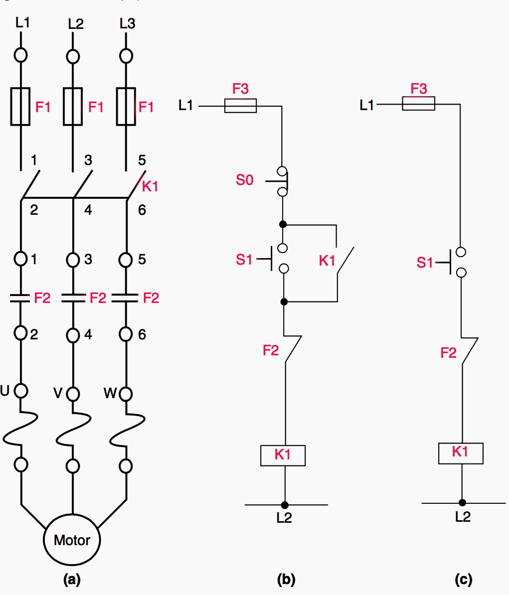
Troubleshooting Three Basic Hardwired Control Circuits Used
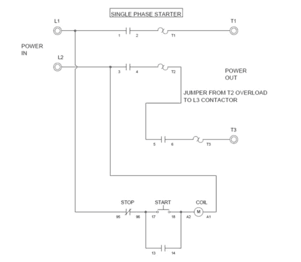
Single phase start stop motor control diagram. Pilot light l2 4 2 3 pilot light start stop bulletin 1495 normally closed auxiliary contacts are required. This diagram is for single phase motor control. T w 6. It uses a contactor an overload relay one auxiliary contact block a normally open start pushbutton a normally closed stop pushbutton and a power supply with a fuse. With the motor running contacts are open. Single phase motor wiring diagram forward reverse single phase motor wiring diagram with capacitor start throughout rh natebird me.
Sometimes it is necessary to control a load from more than one location. For push button control stations 7 start stop control wiring diagrams single station with motor stopped pilot light l1 start l2 i 1 stop 2 oi 3 n wol. Click here to view a capacitor start motor circuit diagram for starting a single phase motor. Properly connect a single phase motors to a three phase starter. Multiple startstop stations controlling a motor. C i m nc.
Wye delta open transition 3 phase motors. Wondering how a capacitor can be used to start a single phase motor. The start and stop circuits could alternatively be controlled using a plc. We hope this helps further your understanding of motor controls. The below wiring diagram shows how we would assemble a complete motor starter with a startstop button for a single phase motor utilizing a 3 pole contactor. Also read about the speed torque characteristics of these motors along with its different types.
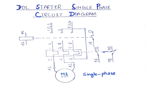
In the above one phase motor wiring i first connect a 2 pole circuit breaker and after that i connect the supply to motor starter and then i do cont actor coil wiring with normally close push button switch and normally open push button switch and in last i do connection between capacitor. Capacitor start capacitor run induction motors are single phase induction motors that have a capacitor in the start winding and in the run winding as shown in figure 12 and 13 wiring diagram. The above diagram is a complete method of single phase motor wiring with circuit breaker and contactor. Pressing the stop pushbutton breaks the control voltage through the memoryseal in contact causing the coil to de energized which open the line voltage to the loads turning it off. This type of motor is designed to provide strong starting torque and strong running for applications such as large water pumps.


