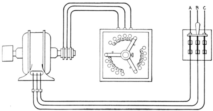
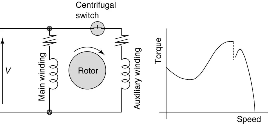
Electric control motor repair click for larger image. Adjusting the resistance allows control of the speedtorque characteristic of the motor.
Starting Of Slip Ring Induction Motor Explained In An Easy
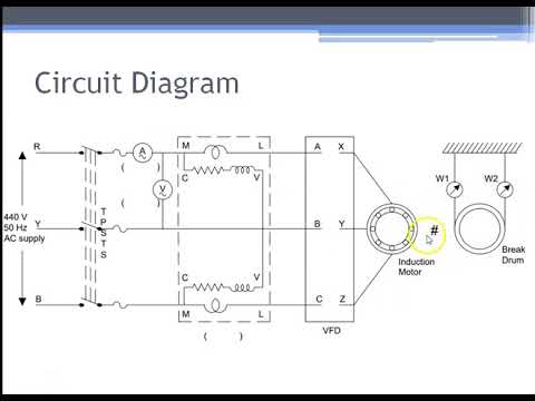
Slip ring induction motor wiring diagram. And its based on the approximate equivalent circuit. It consists laminated cylindrical core which has a semi closed slot at the outer periphery and carries three phase insulated winding. As discussed earlier a slip ring induction motor is an asynchronous motor as the rotor never runs in synchronous speed with the stator poles. A slip ring is an electromechanical device that allows the transmission of power and electrical signals from a stationary to a rotating structure. A wound rotor motor also known as slip ring rotor motor is a type of induction motor where the rotor windings are connected through slip rings to external resistance. Three phase motor control installation wiring diagrams.
The frame voltage is the open circuit voltage when the rotor is not rotating and gives the measure of turns. This reduces the phase difference angle and the current induced approaches the maximum torque condition. It can improve mechanical performance simplify system operation and eliminate damage prone wires dangling from movable joints. Bharat bijlee ltd non sparking motors ex n. The rotor is wound for the same number of poles as that of the stator. This way slip ring induction motors will be able to produce high torque even as they are starting.
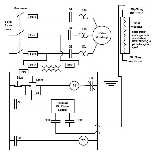
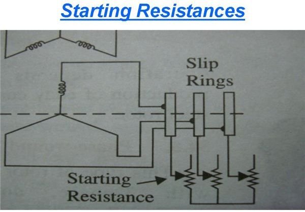
As a slip ring induction motor starts the external resistance value is increased fig11. As the motor accelerates. Three phase slip ring rotor starter control power diagrams 3 phase slip ring rotor starter control power diagrams slip ring rotor power and control. The slip ring induction motor could be used for industrial wires where variable speed and high starting torque are prime requirements. Before deepen in steps of drawing the diagram it. Jr slip ring induction motor jr.
The stator circuit is rated as same in the squirrel cage motor but the rotor is rated in frame voltage or short circuit current. The slip ring induction motor has two distinctly separate parts one is the stator and other is the rotor. The construction of a stator is the same for both the squirrel cage and slip ring induction motor. Check more diagrams here. Motorised conventional type liquid resistance starter to start the slipring induction motor youtube. Wound rotor motors can be started with low inrush current by inserting high resistance into the rotor circuit.
The circle diagram is a graphic representation of the performance of the machine and its drawn in terms of the locus of the input voltage and current. To understand the circle diagram of induction motor we should first know what is the circle diagram. The motor which employing the wound rotor is known as a slip ring induction motor or phase wound motor. A slip ring can be used in any electromechanical system that requires rotation while transmitting power or signals. The stator of slip ring induction motor is very much the same as that of the squirrel cage induction motor but the construction of its rotor is very much differentstator winding can be either star or delta connected depending upon the design. Slip ring induction motor suppliers and manufacturers at alibaba.
Circle diagram of induction motor. Learn more about the construction and operation of a slip ring induction motor. Automatic ups inverter wiring connection diagram to the home. Cg slip ring motors lv low voltage.
Gallery of Slip Ring Induction Motor Wiring Diagram