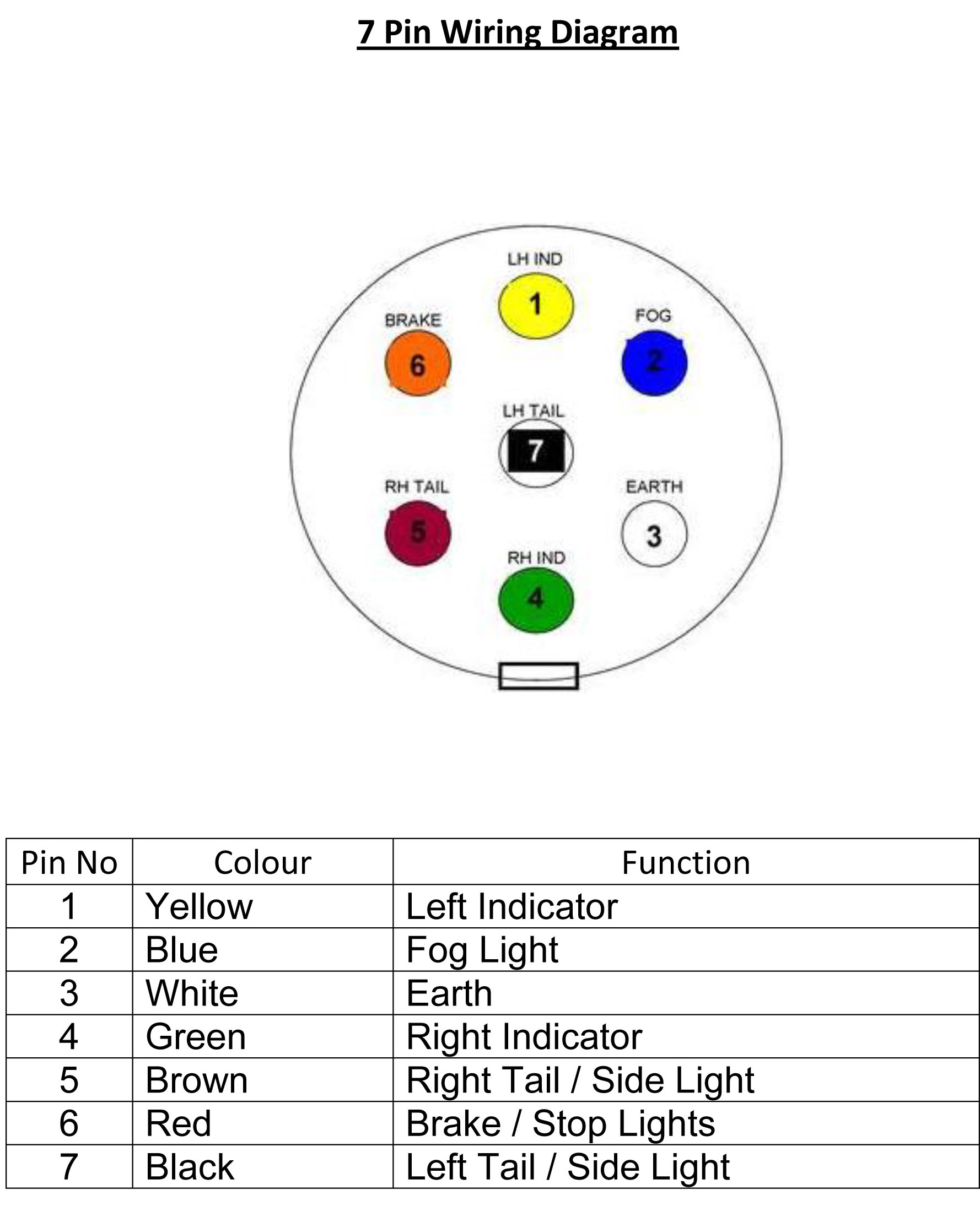
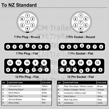
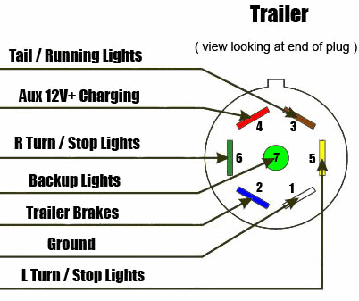
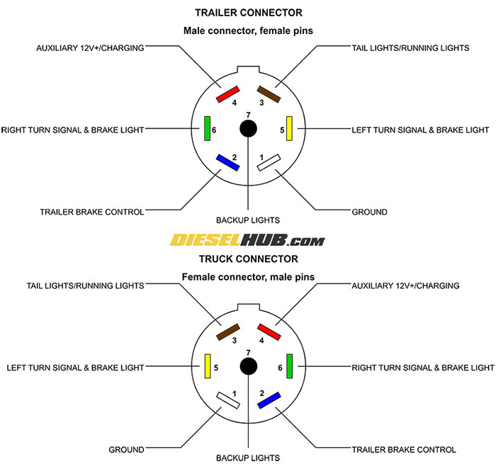
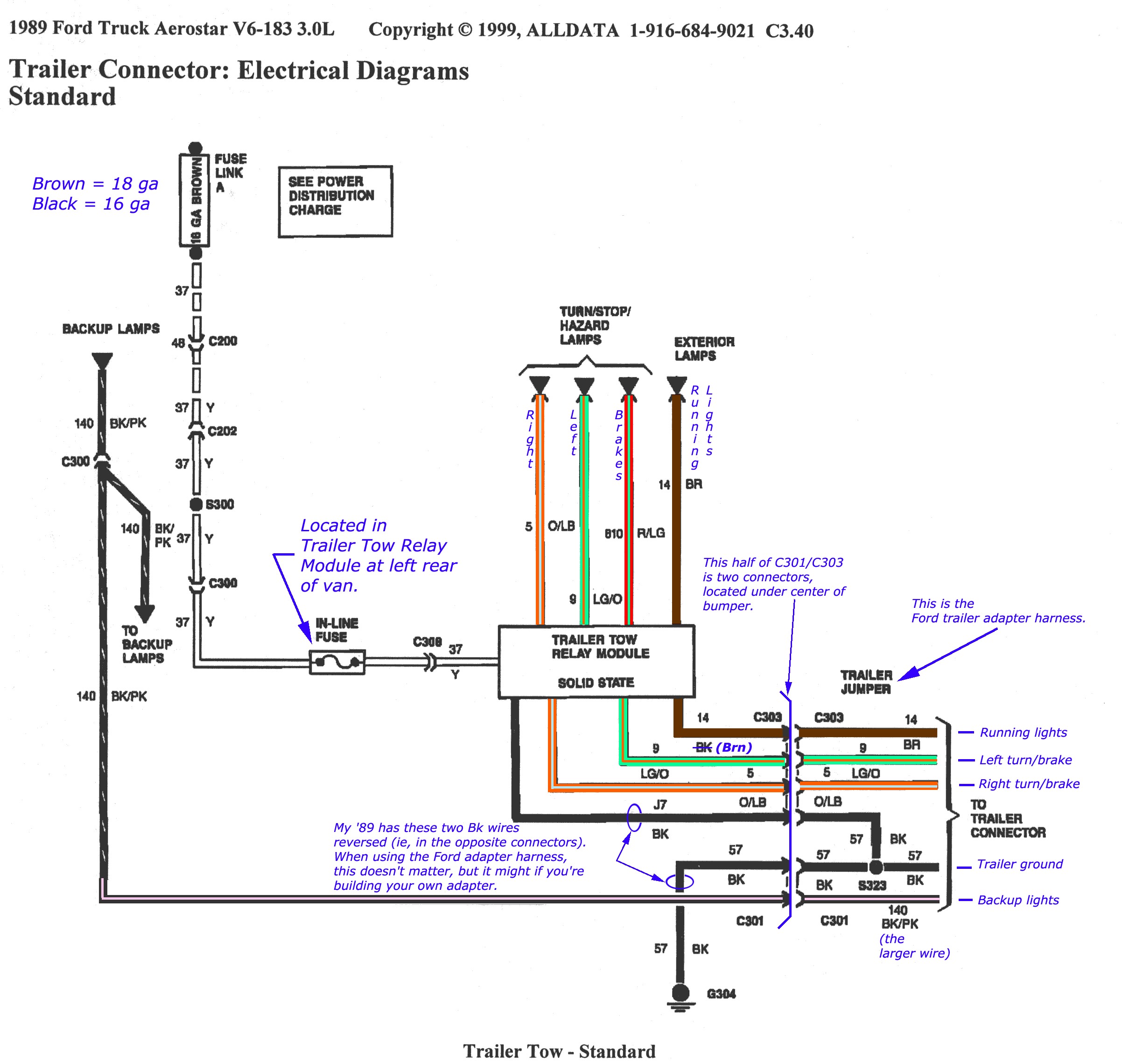
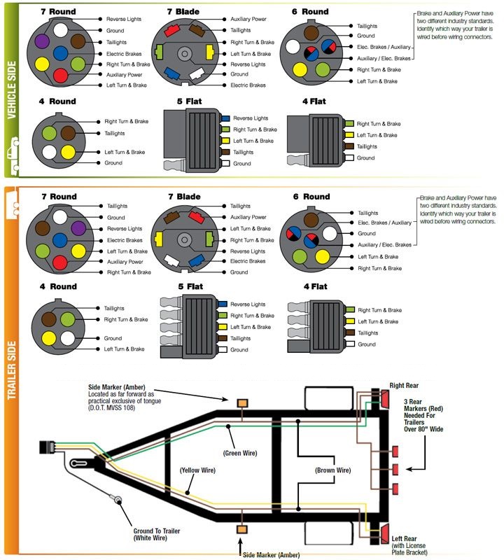
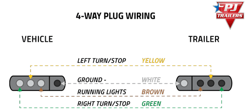
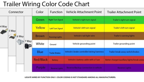
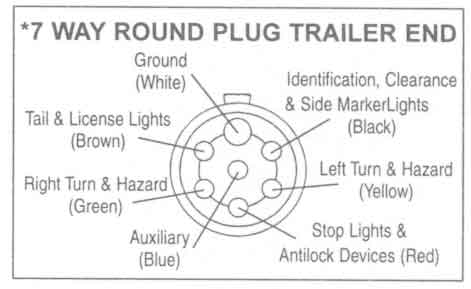
In the trailer wiring diagram and connector application chart below use the first 5 pins and ignore the rest. Another way is to have an adapter that goes from the trailer 5 pin to a standard 7 pin with 2 wires left blank.
Trailer Wiring Diagram And Installation Help Towing 101
Standard trailer plug wiring diagram. Use this handy trailer wiring diagram for a quick reference for various electrical connections for trailers. This vehicle to trailer wiring harness creates a standard trailer wiring connection by plugging into vehicle harness and tail light assembly and then routing the 4 way harness to the rear end of a vehicle. 6 way system rectangle plug. 7 way plug wiring diagram standard wiring post purpose wire color tm park light green battery feed black rt right turnbrake light brown lt left turnbrake light red s trailer electric brakes blue gd ground white a accessory yellow this is the most common standard wiring scheme for rv plugs and the one used by major auto manufacturers today. If you own an older vehicle chances are it will have neither trailer package factory installed nor t connectors available for it. The red and blue wire can be used for brake control or auxiliary.
Some vehicles send only one signal per wire. Use on a small motorcycle trailer snowmobile trailer or utility trailer. Converter for use with vehicles that have separate turn and brake light wires. 34 inch by 1 inch 6 way rectangle connectors right turn signal green left turn signal yellow taillight brown ground white. Trailer wiring diagram wiring diagrams for trailers international 1 989 755 0561 toll free 1 800 358 4751 covid 19. Standard 4 pole wiring harness for use with vehicles that have adequate power and standard wiring system these simply connect into existing wires on the vehicle and have a 4 pole flat connector to attach a trailer.
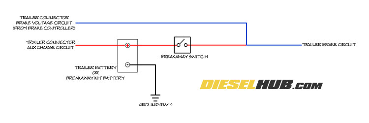
That way the trailer brakes are ready if the tow vehicle has a 7 pin connector.
